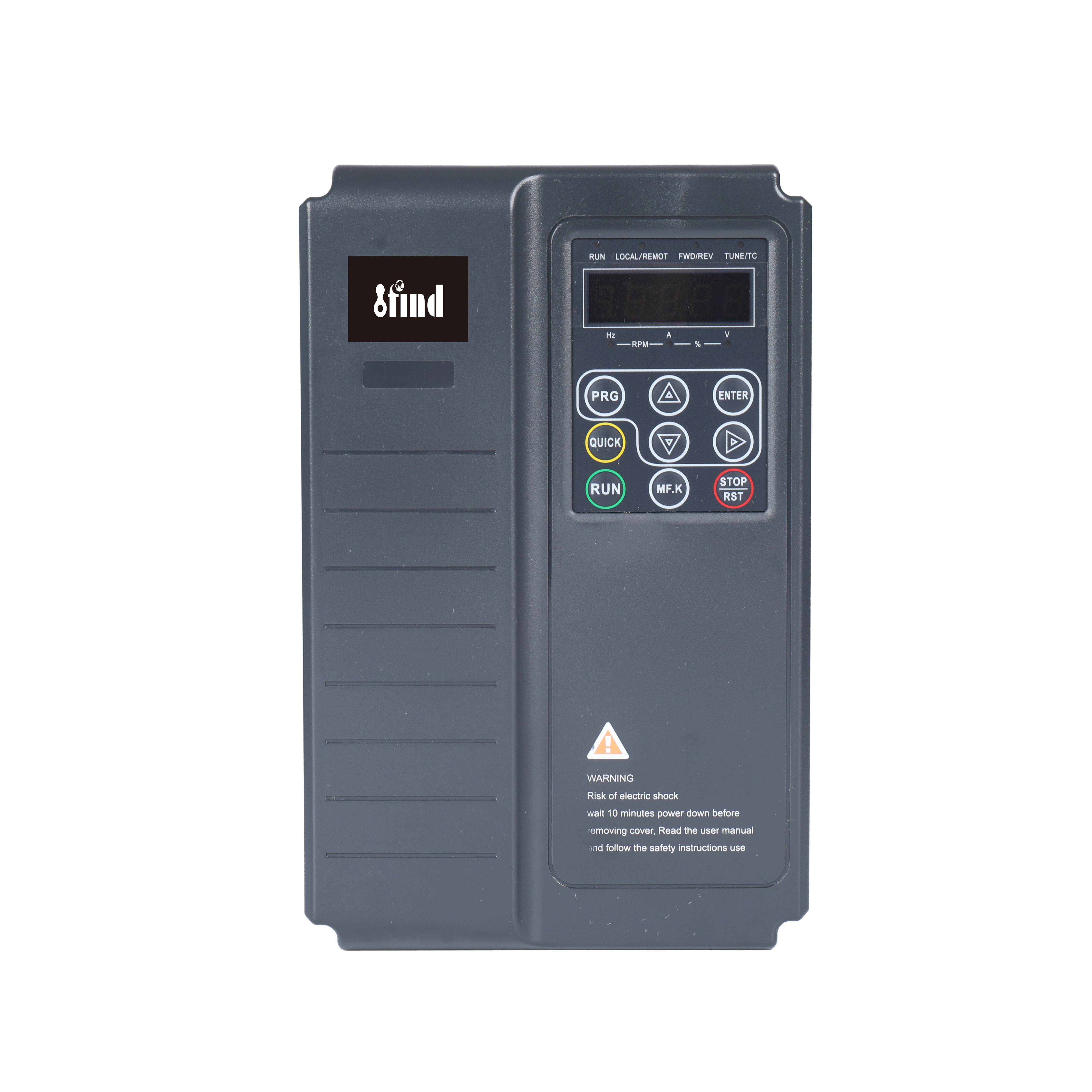
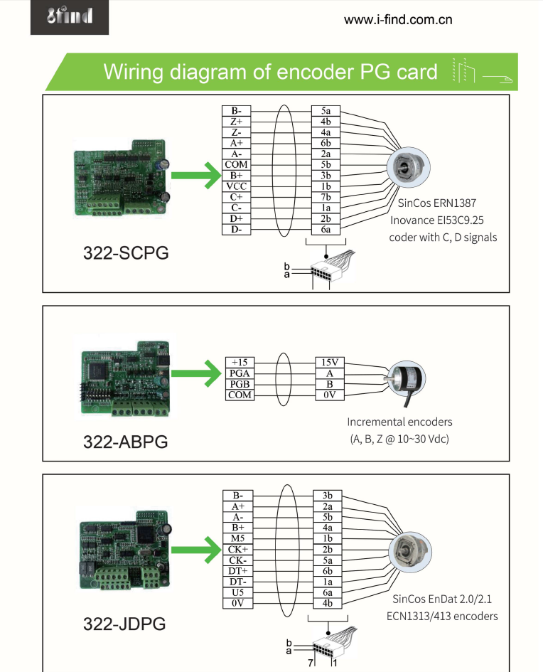
SD320L Closed-Loop Elevator Inverter with Sin/Cos 1387 PG Card
The SD320L is a closed-loop elevator inverter for compatible asynchronous induction motors and permanent magnet synchronous motors. It supports optional AB, ABZ, EnDat 1313, and Sin/Cos 1387 PG cards for encoder feedback. With motor auto-tuning, multi-segment S-curves, startup pre-torque, brake and contactor control, speed monitoring, and 48V emergency evacuation support, it suits geared and gearless lift systems.
IFIND Close Loop Inverter Hot Sales in Middle East Inversor ac Drive power inverter speed controller Inverter are high performance closed loop vector vvf inverters, designed for elevators, for controlling asynchronous AC induction motors and permanent magnet synchronous motors. They apply the most advanced senseless vector vvvf control which follow the leading international level. They are suitable for Villa elevators, residential elevators, commercial elevators, cargo elevators and various speed occasions, it is adapable with multiple of PG cards(AB, ABZ, Endat 1313, Sin/Cos 1387) for gearless and gear motor.Special suitable for heidenhain encode ,it also can be support industry UPS software and home UPS software.use the higher torque functions to achieve the stable of the elevator motor.
Main Features Of Made in china China factory asynchronous 1387 PG card Close Loop drive Inverter
1. Drive both the asynchronous motor and permanent magnetic synchronous motor (PMSM), and provide multiple encoder interfaces. 2. Support motor auto-tuning (static auto-tuning and complete auto-tuning). 3. Support multiple speed sources, multi-speed and analog setting. 4. Guarantee good elevator riding comfort with flexible startup curves, multi-segment S-curve setting, and four groups of acceleration/deceleration time. 5. Support emergency evacuation at power failure with the 48 V battery power supply. 6. Provide various elevator-related functions, including enable detection, brake contactor control, output contactor control, slow-down judgment, overspeed protection, speed deviation detection, door preopen, contact stuck detection, motor overheat detection, and startup pre-torque compensation. 7. Support connection to the external operation panel through the RJ45 interface, making the operation and commissioning simpler and easier. 8. Provide the built-in DC reactor and braking unit, which improves the output power factor and reduces costs of peripheral devices. 9. Separate air duct with conformal coating process, professional manufacturing platform, and advanced process make good product quality. 10.Have the lightning protection design and the strong anti-interface capability, compliant with the EMC standard.
11.Support Synchronous and asynchronous motors.
12. Suitable Heidenhain encoder. use 1387 PG card.
13.Support industry UPS and home UPS.
IGBT
STARPOWER/ INFINEON/FUJI
FAN
PELKO/NIDEC
CAPACITORS
RUBYCON/JIANGHAI
ELECTRONIC
DELTA
Technology support of China factory asynchronous 1387 PG card Close Loop drive Inverter
Voltage class
220VAC
380 to 480AC
Drive Model
SD320L
3.7KW-2
SD320L
5.5KW-2
SD320L
7.5KW-2
SD320L
3.7KW-4
SD320L
5.5KW-4
SD320L
7.5KW-4
SD320L
11KW-4
SD320L
15KW-4
Dimension
Height
Width
Depth
[H]:250mm
[W]:160mm
[D]:183mm
[H]:320mm
[W]:220mm
[D]:183mm
[H]:250mm
[W]:160mm
[D]:183mm
[H]:320mm
[W]:220mm
[D]:183mm
Mounting Hole
Ф5
Ф6
Ф5
Ф6
Drive Input
Rated Input Voltage
Three-phase 200Vac to 240Vac,-15% to +10%
(170Vac to 264Vac)
Three-phase 380Vac to480Vac,-15% to +10%
(323Vac to 528Vac)
Rated Input Current,[A]
10.5
14.6
26
35
10.5
14.8
20.5
29
36
Rated Input Frequency
50/60Hz,±5%(47.5 to 63Hz)
Drive Output
Applicable Motor
[kW]
2.2
3.7
5.5
7.5
3.7
5.5
7.5
11
15
[HP]
3
5
7.5
10
5
7.5
10
15
20
Output Current,[A]*1
9
13
25
32
9
13
18
27
33
Power Capacity,[kVA]
5.9
8.9
17
21
5.9
8.9
11
17
21
Overload Capacity
150% for 60 Sec &180% for 3 Sec
Max. output voltage
Three-phase 200Vac to 240Vac
(Proportional to input voltage)
Three-phase 380Vac to 480Vac
(Proportional to input voltage)
Max. output frequency
100 Hz
Braking
Resistor
Recommended
power,[W]
500
750
1200
1500
750
1200
1500
2500
3000
Recommended
Resistance,[Ω]
≥65
≥45
≥22
≥16
≥130
≥90
≥65
≥43
≥32
Enclosure
IP 21
PG CARD OPTIONS
IFIND asynchronous 1387 PG card Close Loop drive Inverter is a high performance closed loop vector control AC drive, designed for elevators to control asynchronous AC induction motors and permanent magnet synchronous motors. it can be suitable for AB pg card,ABZ pg card,1313 pg card or 1387 pg card.Special for Heidenhain encode.The advanced senseless vector control technology which follow the leading international level is applied for this elevator inverter.if u have big interesting with us,we will support and help u extend your market with our brand or your brand,creat the unique brand advantage,not copy anyone else.it can keep your profit.It is your best choice and good partner for industry control application.
Product Overview
The SD320L is a closed-loop elevator inverter developed for speed and torque control in lift systems using encoder feedback. It supports compatible asynchronous AC induction motors and permanent magnet synchronous motors, allowing the drive configuration to be matched to geared or gearless elevator systems.
Multiple PG card options are available for AB, ABZ, EnDat 1313, and Sin/Cos 1387 encoder signals. When equipped with the appropriate card, the inverter receives motor position or speed feedback and uses this information to regulate motor output in real time.
The SD320L combines closed-loop vector control, motor auto-tuning, flexible S-curve settings, startup pre-torque compensation, brake and contactor control, speed monitoring, emergency evacuation support, and elevator-specific fault detection. Available configurations cover three-phase 200–240V and three-phase 380–480V power systems.
The inverter controls the elevator motor but does not replace the elevator controller, mechanical brake, overspeed governor, safety gear, door interlocks, or other safety devices required by the complete lift system.
Closed-Loop Vector Control
Encoder Feedback Control
In a closed-loop system, the motor encoder returns actual speed or position information to the inverter through a compatible PG card. The drive compares this feedback with the commanded value and adjusts motor current, torque, and speed accordingly.
Compared with encoder-free control, correctly commissioned closed-loop vector control can provide:
More accurate low-speed regulation
Improved response to load changes
Controlled starting torque
More stable speed transitions
Better coordination at starting and stopping
More consistent leveling performance
Improved control of geared and gearless motors
Actual performance depends on the motor, encoder resolution, PG card, mechanical system, controller commands, brake timing, parameter settings, and commissioning quality.
Low-Speed Elevator Operation
Elevators require controlled operation during startup, inspection, deceleration, and floor approach. Encoder feedback allows the SD320L to monitor actual motor movement during these low-speed stages.
Closed-loop control does not independently determine the car position or floor location. Floor selection, leveling commands, door operation, terminal limits, and safety logic remain the responsibility of the elevator controller and associated sensors.
Startup Pre-Torque Compensation
Before the mechanical brake opens, the drive can establish motor torque according to the configured startup sequence. This helps reduce unintended rollback or abrupt movement when the brake is released.
Pre-torque parameters must be coordinated with:
Car load
Counterweight ratio
Motor type
Traction arrangement
Brake opening delay
Torque direction
Encoder direction
Elevator controller signals
Incorrect torque direction or brake timing can cause unexpected motor movement. Initial testing should therefore be performed under controlled commissioning conditions.
PG Card and Encoder Options
The SD320L supports multiple encoder interfaces through dedicated PG card options.
PG Card Option
Typical Feedback Type
Selection Requirement
AB PG Card
Incremental two-channel pulse feedback
Confirm signal level, pulse count and power supply
ABZ PG Card
Incremental AB feedback with Z reference
Confirm Z-channel requirements and electrical format
EnDat 1313 PG Card
Compatible EnDat encoder feedback
Confirm encoder model, protocol and cable
Sin/Cos 1387 PG Card
Compatible sinusoidal encoder feedback
Confirm signal specification and encoder power supply
Sin/Cos 1387 Feedback
The Sin/Cos 1387 PG card is intended for compatible encoders used in elevator motor control. The card processes the encoder feedback signals and transfers the required motor feedback information to the SD320L.
Before selecting this option, provide:
Complete encoder manufacturer and model
Encoder interface type
Encoder supply voltage
Sin/Cos signal specification
Number of signal periods or pulses
Motor type
Encoder cable definition
Connector pinout
Cable length
Shielding and grounding method
The term “1387 encoder” alone is not sufficient to confirm compatibility. The exact electrical interface and encoder documentation should be reviewed before ordering.
EnDat 1313 Feedback
EnDat 1313 and Sin/Cos 1387 encoders do not necessarily use the same communication and feedback method. The correct PG card must be selected for the installed encoder.
A PG card should not be chosen only because the connector appears mechanically compatible. Signal type, power supply, communication, pin definition, grounding, and inverter firmware must all be checked.
Encoder Installation
Encoder cables should be routed separately from motor output cables and other high-current conductors. Shielding and grounding should follow the inverter, encoder, and control-panel requirements.
During commissioning, confirm:
Encoder power supply
Encoder signal type
PG card installation
Cable pin assignment
Motor rotation direction
Encoder feedback direction
Feedback value at low speed
Absence of signal-loss or speed-deviation faults
Asynchronous and PMSM Motor Control
Asynchronous Induction Motors
The SD320L can control compatible asynchronous AC induction motors used in geared elevator systems. Motor nameplate data and encoder information must be entered before auto-tuning.
Required motor data normally include:
Rated voltage
Rated current
Rated power
Rated frequency
Rated speed
Power factor
Encoder type
Encoder pulse or signal data
Permanent Magnet Synchronous Motors
The inverter also supports compatible permanent magnet synchronous motors commonly used in gearless elevator systems.
PMSM commissioning requires additional attention because correct rotor-position and encoder information are essential for torque production. The exact motor and encoder combination should be confirmed before selecting the inverter and PG card.
Motor identification and initial rotation tests must be conducted according to the applicable commissioning procedure. Incorrect encoder offset, wiring, phase sequence, or feedback direction may cause abnormal torque or startup failure.
Motor Auto-Tuning
The SD320L supports static and complete motor auto-tuning.
Static auto-tuning may be used when the motor cannot rotate freely, subject to the limitations specified in the operating manual. Complete auto-tuning generally requires controlled motor rotation and must only be performed when the elevator is placed in an appropriate commissioning state.
Before auto-tuning:
Verify motor wiring
Confirm encoder wiring
Check the mechanical brake
Isolate normal passenger operation
Confirm the car and counterweight condition
Enter accurate motor data
Follow the applicable elevator safety procedure
Elevator Motion Control
Flexible S-Curve Settings
The SD320L provides flexible startup curves, multi-segment S-curve settings, and four groups of acceleration and deceleration times.
These settings allow the commissioning technician to coordinate:
Starting response
Normal acceleration
Constant-speed travel
Deceleration
Leveling approach
Final stopping
Inspection operation
Emergency operation
An S-curve reduces the rate of acceleration change, but ride comfort cannot be determined by the inverter setting alone. Guide-rail condition, traction components, brake operation, car balance, controller commands, and mechanical installation also affect passenger experience.
Multiple Speed References
The drive supports multiple speed sources, including multi-speed and analog settings. The final command arrangement should be defined according to the elevator controller.
Speed stages may be assigned for:
Inspection speed
Creep speed
Leveling speed
Normal travel
Reduced-speed operation
Emergency evacuation
Signal priority and transition logic should be checked to prevent conflicting commands.
Slow-Down Judgment
The SD320L provides elevator-related slow-down judgment functions. These functions support the control sequence but do not replace terminal limit switches, floor-position signals, or other independent safety devices.
The required deceleration distance should account for car speed, load, brake condition, traction system, controller logic, and applicable elevator standards.
Door Pre-Opening Support
Door pre-opening may be supported as part of a properly designed elevator system. This function must only operate when all required speed, position, leveling-zone, brake, controller, and safety conditions are satisfied.
The inverter alone must not be used as the only device that determines whether door opening is safe.
Brake and Contactor Control
Brake Contactor Control
The SD320L provides functions for coordinating motor torque with mechanical brake operation. A typical sequence includes:
Receive the run command.
Establish the required motor current or torque.
Issue the brake release command.
Confirm the brake or contactor feedback.
Accelerate according to the selected curve.
Decelerate at the destination.
Reduce speed to the stopping stage.
Apply the mechanical brake.
Remove motor torque after the required delay.
The exact sequence must be defined by the elevator controller and system design.
Output Contactor Control
The inverter supports output-contactor control and contact-stuck detection. An output contactor must not be opened while the inverter is actively supplying motor current unless the approved safety sequence specifically requires it.
Improper contactor operation can generate faults or damage electrical components.
Enable Detection
Enable detection helps confirm that the required operating permission is present before motor output begins. Enable logic should be coordinated with the elevator controller, safety circuit, brake feedback, and contactor status.
Emergency Evacuation at Power Failure
The product page states that the SD320L supports emergency evacuation using a 48V battery power supply.
This function may allow a compatible elevator system to move toward a designated floor or safe release position after normal AC power is lost. The complete emergency system may require a battery, switching equipment, controller logic, brake supply, door power, charging circuit, and other external components.
Before applying this function, confirm:
Supported SD320L models
48V input terminal and permitted range
Battery type and capacity
Required evacuation direction
Maximum load
Motor compatibility
Permitted travel speed
Brake power arrangement
Elevator controller sequence
Number of expected rescue operations
The phrase “supports 48V emergency evacuation” should not be interpreted as meaning the inverter alone forms a complete automatic rescue device.
Setup and Commissioning
Pre-Commissioning Checks
Before energizing the inverter, verify:
Input voltage and phase
Protective grounding
Motor wiring
Motor insulation condition
Brake circuit
Contactor circuit
PG card model
Encoder wiring
Encoder power supply
Control terminal assignments
Emergency stop circuit
Controller communication
Braking resistor specification
Recommended Commissioning Sequence
Confirm the SD320L voltage and current rating.
Enter the complete motor nameplate data.
Select asynchronous motor or PMSM control.
Select the installed PG card and encoder type.
Confirm encoder resolution and signal settings.
Perform the applicable motor auto-tuning procedure.
Test motor and encoder directions at low speed.
Verify brake release and closing timing.
Test inspection operation.
Configure startup pre-torque.
Adjust acceleration, deceleration and S-curves.
Test normal travel under controlled load.
Verify leveling and stopping response.
Test fault handling and emergency operation.
Review operating current, speed feedback and fault records.
Passenger service should not begin until the complete elevator system has passed the required inspection and safety testing.
Drive and Elevator Protection
The SD320L includes elevator-related monitoring and protection functions such as:
Overspeed protection
Speed-deviation detection
Encoder feedback monitoring
Brake-contactor control
Output-contactor control
Contactor-stuck detection
Motor-overheat detection
Enable detection
Drive overcurrent protection
Drive overvoltage protection
Undervoltage protection
Overload protection
Inverter overtemperature protection
When a fault occurs, the technician should identify the root cause before resetting the inverter. Repeatedly clearing a speed-deviation or encoder fault without checking the encoder, motor direction, brake, and mechanical load may create additional risk.
System Safety Boundary
The SD320L controls motor operation but does not replace:
Mechanical brake
Overspeed governor
Safety gear
Door interlocks
Landing-door locks
Terminal limit switches
Final limit switches
Emergency stop circuit
Load-monitoring system
Inspection controls
Elevator safety controller
Other code-required safety components
Safety functions must be implemented and validated according to the applicable elevator regulations.
Elevator Applications
Villa Elevators
The SD320L can be applied to compatible villa elevators requiring encoder-based motor control. Selection should consider available power, motor type, travel height, rated speed, capacity, and rescue requirements.
Residential Passenger Elevators
Closed-loop control supports residential lift systems where controlled starting, speed transitions, stopping, and leveling are required under changing passenger loads.
Commercial Elevators
Commercial buildings may require more frequent starts, higher traffic levels, and closer coordination with the elevator controller. Drive current, thermal duty, braking energy, and operating frequency should be assessed for the project.
Cargo Elevators
Cargo lifts can produce large and changing load conditions. The inverter should be selected using motor current, overload demand, load imbalance, travel speed, braking duty, and required starting torque.
Geared Elevator Systems
Compatible asynchronous motors with incremental encoder feedback can be used in geared elevator configurations. The PG card must match the installed encoder.
Gearless Elevator Systems
Compatible PMSMs with Sin/Cos 1387, EnDat 1313, or another supported encoder may be used in gearless systems. Motor and encoder documentation should be reviewed together before confirming the configuration.
Technical Specifications
General Performance
Parameter
Specification
Product Series
SD320L
Control Type
Closed-loop vector elevator drive
Supported Motors
Compatible asynchronous induction motors and PMSMs
Encoder Options
AB, ABZ, EnDat 1313 and Sin/Cos 1387
Motor Auto-Tuning
Static and complete auto-tuning
Speed Settings
Multiple speed sources, multi-speed and analog setting
Motion Profiles
Multi-segment S-curves
Acceleration/Deceleration
Four configurable groups
Overload Capacity
150% for 60 seconds; 180% for 3 seconds
Maximum Output Frequency
100Hz
Emergency Operation
48V battery evacuation support
External Keypad
RJ45 interface
Enclosure
IP21
Braking Unit
Built-in according to the original product description
DC Reactor
Built-in according to the original product description
Available Models
Voltage Class
Drive Model
Applicable Motor
220V
SD320L 3.7KW-2
2.2kW
220V
SD320L 5.5KW-2
3.7kW
220V
SD320L 7.5KW-2
5.5kW
220V
SD320L 3.7KW-4*
Requires technical confirmation
380–480V
SD320L 5.5KW-4
3.7kW
380–480V
SD320L 7.5KW-4
5.5kW
380–480V
SD320L 11KW-4
7.5kW
380–480V
SD320L 15KW-4
11kW or 15kW—confirm model table
Electrical Data
Parameter
220V Class
380–480V Class
Rated Input
Three-phase 200–240VAC
Three-phase 380–480VAC
Permitted Input Range
170–264VAC
323–528VAC
Input Frequency
50/60Hz, ±5%
50/60Hz, ±5%
Maximum Output Voltage
Three-phase 200–240VAC, proportional to input
Three-phase 380–480VAC, proportional to input
Maximum Output Frequency
100Hz
100Hz
Enclosure
IP21
IP21
The drive should be selected according to motor rated current and overload requirements, not only by comparing the motor kW with the model name.
Quality and Engineering Support
The SD320L uses a separated air-duct structure and conformal-coating process. The original page also lists built-in braking and DC-reactor functions, subject to confirmation for each model.
IFIND provides technical support for:
Inverter model selection
Asynchronous motor matching
PMSM matching
PG card selection
Encoder compatibility review
Motor auto-tuning
Brake-sequence configuration
S-curve adjustment
Emergency evacuation setup
Fault diagnosis
Elevator controller integration
For project evaluation, customers should provide the motor nameplate, encoder datasheet, elevator load, rated speed, traction arrangement, controller signals, input supply, braking resistor requirements, and emergency rescue design.
FAQs
What is the difference between open-loop and closed-loop elevator control?
Closed-loop control uses encoder feedback to monitor actual motor operation. This generally provides better low-speed response and speed regulation than encoder-free control. Open-loop control does not require an encoder but cannot provide the same feedback-based correction.
Is a Sin/Cos 1387 PG card included as standard?
The original page lists several PG card options. The required card should be confirmed in the quotation because AB, ABZ, EnDat 1313, and Sin/Cos 1387 interfaces are different.
Can the SD320L control an asynchronous motor?
Yes. It supports compatible asynchronous AC induction motors when the motor, encoder, voltage, current, and PG card are correctly matched.
Can it control a permanent magnet synchronous motor?
Yes. The page states that compatible PMSMs are supported. The motor parameters, encoder interface, rotor-position information, and commissioning method must be confirmed.
Can the same PG card be used for every encoder?
No. The PG card must match the encoder’s signal type, voltage, pinout, resolution, communication method, and cable.
Does every Heidenhain encoder use the 1387 interface?
No. Heidenhain manufactures encoders with different interfaces. The complete encoder model and datasheet are required before selecting a PG card.
What information is needed to select the correct PG card?
Provide the encoder manufacturer, complete model, signal type, supply voltage, pulse or signal-period data, connector pinout, motor model, and cable length.
Does the SD320L include a braking unit?
The original product page states that a braking unit is built in. However, this should be confirmed for the exact power model, together with the required external braking resistor.
Can the inverter perform emergency rescue during a power failure?
The page states that it supports evacuation with a 48V battery supply. The complete rescue configuration, battery capacity, controller sequence, brake supply, permitted load, and supported models must be confirmed.
Does the inverter replace the elevator controller?
No. It regulates motor speed and torque. The elevator controller manages floor logic, travel commands, doors, brake commands, position signals, rescue logic, and the safety sequence.
Why does an encoder-direction fault occur?
Possible causes include reversed encoder channels, incorrect motor direction, wrong PG card selection, incorrect encoder parameters, wiring faults, poor shielding, signal loss, or an incorrect PMSM rotor-position setting.
How should the drive size be selected?
Use motor rated current, overload demand, elevator capacity, rated speed, counterweight ratio, motor type, braking duty, travel frequency, and installation temperature. Motor power alone is insufficient.
Need an SD320L Matched to Your Motor and Encoder?
Send us the motor nameplate, encoder model, elevator capacity, rated speed, input voltage, and controller requirements. Our team will review the inverter rating and PG card configuration for your lift project.
VF and VECTOR VFD inverter are already widely used in the world, The software is powerful and has a variety of control methods. Built-in PID, simple PLC; The inverter has the advantages of good speed regulation performance, high efficiency, stable performance, high reliability, strong overload capacity, etc., widely used in weaving, chemical fiber, printing and dyeing, plastics, light industry, machinery, chemical, steel, paper and other industries application
Solar inverter are already widely used in the world, Series applies to transforming three phase 380V or Single phase 220V submersible deep well pump into solar water pump system. It works this way that direct current produced by solar module inputs into alternating current which drives all kinds of water pump, especially for submersible well pump. Agricultural irrigation is carried out by directly connecting solar panels to drive water pumps
Elevators are already widely used in buliding,both for Synchronous and asynchronous motors the control functions and operation comfortable is much more and more important, our elevator inverter suitables for passenger and cargos, use the PMW and V/F ,vector control. Adopt international advanced V/F and vector technology Programmable Open Collector Output, Relay Output, Analog Output, Programmable Digital Input, Ensure the smooth and safe operation of the elevator.
Hybrid inverter are already widely used in the world, MPPT Solar Hybrid Inverter is a new all-in-one hybrid solar charge inverter, which integrates solar energy storage &means charging energy storage and AC sine wave output.It can be accessed to a variety of household appliances and office loads, power tools, industrial equipment, and electronic audio and video equipment, including refrigerators, lamps, televisions, fans, air conditioning and other AC loads