You are here: Home / Products / Elevator Inverter / SD310L Open-Loop Elevator Inverter with Sensorless Vector Control
loading
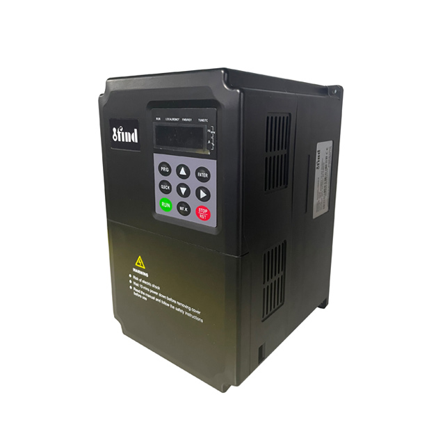
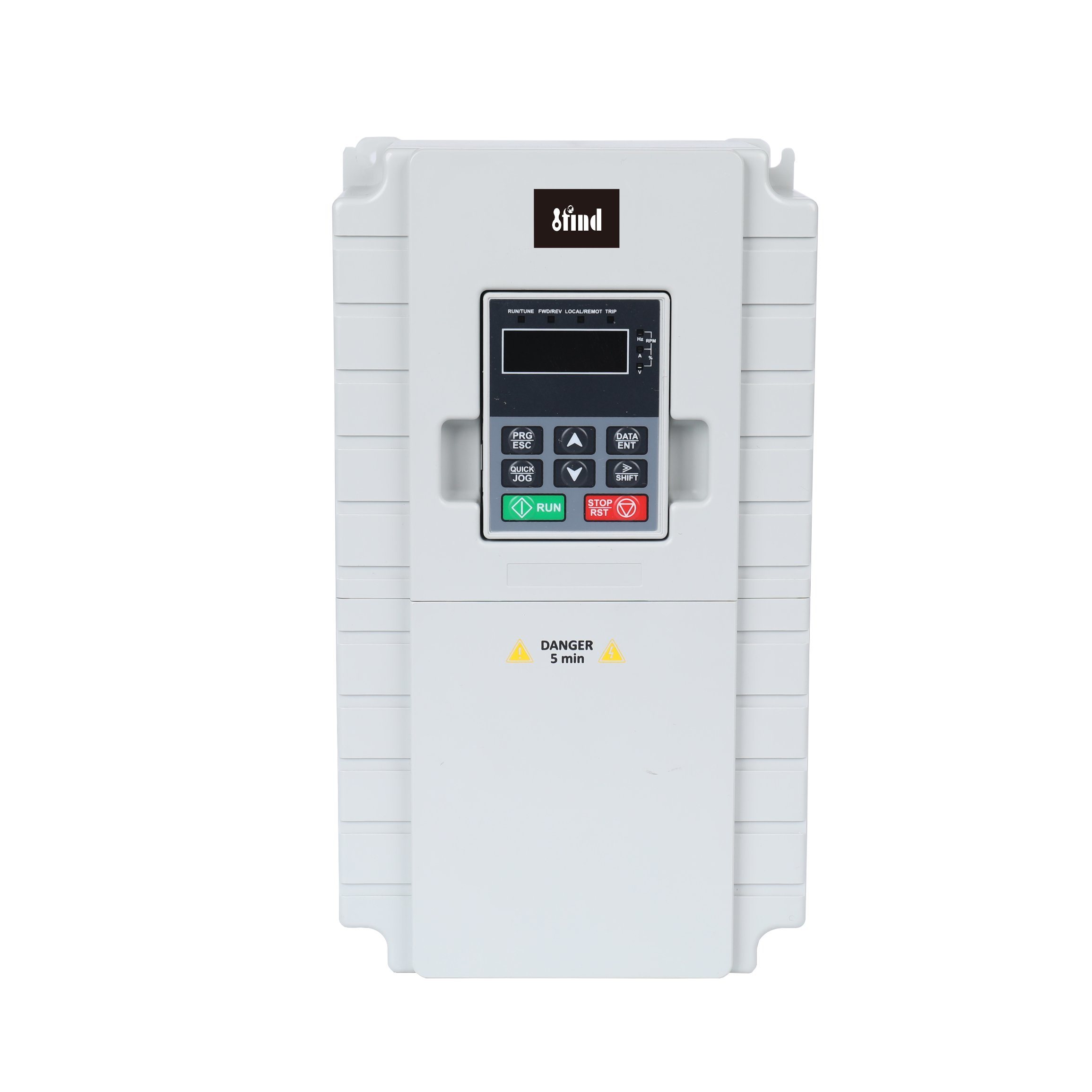
SD310L Open-Loop Elevator Inverter with Sensorless Vector Control
The IFIND SD310L is an open-loop elevator inverter for passenger and freight lift motor control. It combines sensorless vector and V/F control with 150% starting torque at 0.5Hz, a 1:100 speed range, temporary overload capacity, eight-step speed control and programmable I/O. The drive operates without a motor encoder and can be integrated with a compatible elevator controller.
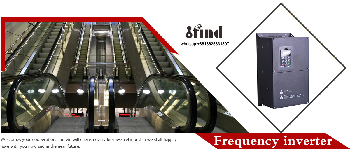
Elevators are already widely used in cargo or passenger application in buliding, the control functions and operation comfortable is much more and more important,our elevator inverter suitables for passenger and cargos,use the PMW and V/F ,vector confrol,Improved operation accuracy and protect the application safety.
Main Features Of Elevator /Lifts/ Escaltaors Power Inverter Inversor De VFD Elevador Frequency Inverter
Control Mode: Sensorless Vector Control (SVC), V/F Control. 2.Overload Capacity: 3.60s with 150% of rated current, 10s with 180% of rated current. 4.Starting Torque: 150% of rated torque at 0.5Hz (SVC). 5.Speed Adjusting Range: 1:100 (SVC) 6.Speed Accuracy: ± 0.5% of maximum speed (SVC) 7.Carrier Frequency: 0.5kHz ~15.0kHz. 8.Reference Frequency Source: keypad, analog input, serial communication, multi-step speed, PID and so on. The combination of 9.multi- modes and switching between different modes can be realized. 10.Torque Control Function: Provide multiple torque setting source. 11.PID Control Function 12.Multi-Step Speed Control Function: 8 steps speed can be set. 13.Traverse Control Function 14.None-Stop when instantaneous power off. 15.Speed trace Function: Start the running motor smoothly. 16.QUICK/JOG Key: User defined shortcut key can be realized. 17.Automatic Voltage Regulation (AVR) Function: 18.Automatically keep the output voltage stable when input voltage fluctuating. 19.Up to 24 fault protections.
Open Loop Elevator Variable Speed Drive Soft Starter VFD Frequency Inverter sales point
1.I/O features 2.Programmable Digital Input:Provide 4 terminals which can accept ON-OFF inputs
3.Programmable Analog Input:FV can accept input of 0 ~10V; FI can accept input of 0~10V or 0~20mA.
4.Programmable Open Collector Output:Provide 1 output terminal (open collector output or high-speed pulse output)
5.Relay Output: Provide 1 output terminal. 6.Analog Output: Provide 1 analog output terminal, whose output scope can be 0/4~20 mA or 0~10 V, as chosen..
IFIND INVERTER product adopts the speed sensorless vvvf control technology and high torque control technology synchronized with the current international leading technology, which not only has the same excellent control performance as the international high-end inverter, but also combines the application characteristics of China to further strengthen the reliability and environmental adaptability of the product as well as the design of customization and construction industry.we are your best partner!
Open-Loop Control for Elevator Systems
The IFIND SD310L is an open-loop elevator inverter developed to control motor speed and torque in passenger and freight lift applications. It operates without motor-speed feedback from a shaft encoder, simplifying the drive configuration in elevator systems where sensorless control provides sufficient operating performance.
The inverter receives operating commands and speed references from the elevator controller, then regulates the connected motor during starting, acceleration, travel, deceleration and stopping.
The SD310L is a motor drive rather than a complete elevator controller. Landing logic, door control, mechanical brake management, safety circuits, limit switches and emergency functions must be handled by suitable external elevator equipment.
Sensorless Vector and V/F Control
The SD310L provides two principal motor-control modes.
Sensorless Vector Control
Sensorless vector control, or SVC, estimates motor operating conditions without requiring encoder feedback. Compared with conventional V/F control, it provides stronger low-speed torque and more controlled speed response.
SVC is intended for lift systems that require:
Loaded starting
Controlled low-speed movement
Stable acceleration
Improved response to changing car loads
Wider speed adjustment
Operation without a motor encoder
Correct motor nameplate data and auto-tuning procedures are important for obtaining the listed sensorless vector performance.
V/F Control
V/F control adjusts motor voltage according to output frequency. It provides a simpler control method for applications where the required torque and speed accuracy are less demanding.
The correct mode should be selected according to the motor, elevator mechanism, operating speed, load variation and required ride performance.
High Starting Torque at Low Speed
Under sensorless vector control, the SD310L provides 150% of rated torque at 0.5Hz. This low-frequency torque capability supports controlled starting when the lift car is loaded.
Low-speed torque is particularly important during the transition between standstill and movement. Insufficient torque or incorrect motor parameters may lead to slow response, current fluctuation or unstable starting.
The final result also depends on:
Motor condition and rated current
Gearbox and traction-machine condition
Counterweight balance
Mechanical brake timing
Car load
Acceleration settings
Motor auto-tuning
Drive sizing
The inverter must not be relied upon to hold the car mechanically at standstill. A correctly designed and controlled mechanical brake remains necessary.
Speed Regulation Performance
The published sensorless vector performance includes a 1:100 speed adjustment range and speed accuracy within ±0.5% of maximum speed.
This allows the elevator controller to command different operating speeds for:
Starting
Normal travel
Approach
Inspection operation
Maintenance jogging
Controlled stopping
The actual car-speed accuracy also depends on the traction system, motor slip, controller commands, mechanical load and commissioning quality.
Open-loop control does not provide the same direct motor-speed feedback as a closed-loop system. Applications requiring very high speed accuracy, zero-speed torque or precise position control should be evaluated separately.
Overload Capacity for Lift Duty
Elevator motors may experience short periods of high current during loaded starting and changes in operating conditions. The SD310L provides the following published overload capacity:
150% of rated current for 60 seconds
180% of rated current for 10 seconds
These ratings allow the drive to handle temporary overloads within the specified time limits. They do not mean the inverter can operate continuously above its rated current.
Drive selection should consider:
Motor nameplate current
Maximum car load
Counterweight ratio
Starts per hour
Travel duration
Acceleration time
Ambient temperature
Installation altitude
Braking demand
Selecting only by motor power may result in an undersized drive. Rated motor current and actual elevator duty should be reviewed together.
Flexible Speed and Command Sources
The SD310L accepts speed references and operating commands from several sources:
Built-in keypad
Analog input
Serial communication
Multi-step speed settings
PID control
Combined command modes
Different sources can be selected or switched according to the elevator-control design.
During normal elevator service, travel commands should usually come from the elevator controller. The keypad and JOG function are more appropriate for commissioning, inspection or maintenance procedures carried out by qualified personnel.
The carrier frequency can be adjusted from 0.5kHz to 15.0kHz. Carrier-frequency selection affects motor noise, switching losses, drive temperature and cable-related electrical effects. It should be set according to the motor, cable length and installation conditions.
Multi-Step and Auxiliary Functions
Eight-Step Speed Control
Up to eight preset speeds can be configured. These settings can support different stages of elevator movement or dedicated inspection and maintenance speeds when coordinated with the main controller.
The complete speed sequence, including acceleration and stopping, must be commissioned according to the elevator mechanism and control logic.
Torque Control
The inverter provides multiple torque-reference sources. Torque settings can be used to limit or regulate motor output according to the operating requirement.
Torque parameters must be adjusted carefully. Incorrect limits may prevent the car from starting normally or may produce excessive current.
Speed Tracking
The speed-tracking function allows the inverter to identify and start a motor that is already rotating. It is intended to reduce the impact that may occur when control is applied to a moving motor.
This function does not replace brake sequencing, zero-speed confirmation or elevator safety logic.
PID and Traverse Functions
The SD310L also lists PID and traverse-control functions. These are general drive functions and are not necessarily required in every elevator installation. Their use should be determined by the control-system designer.
QUICK/JOG Key
The QUICK/JOG key can be assigned as a user-defined shortcut. It can simplify selected commissioning or maintenance operations when enabled by an authorized technician.
Programmable I/O
The SD310L provides programmable control terminals for connection to the elevator controller and related automation devices.
I/O Type
Published Configuration
Programmable digital input
Four terminals for ON/OFF input signals
FV analog input
0–10V
FI analog input
0–10V or 0–20mA
Open-collector output
One programmable output or high-speed pulse output
Relay output
One programmable relay output
Analog output
One output selectable as 0/4–20mA or 0–10V
These terminals may be assigned to command, reference, operating-status or fault functions according to the parameter configuration.
Before wiring, confirm:
Signal voltage and current type
Common-terminal arrangement
Input polarity
Relay contact capacity
Shielding and grounding
Controller signal logic
Fail-safe response to wire disconnection
Signal cables should be routed separately from motor and power cables where practical to reduce electrical interference.
Passenger and Freight Lift Applications
Passenger Elevators
For passenger-lift applications, the SD310L can regulate motor starting, acceleration, travel and deceleration without encoder feedback.
Ride quality depends on the complete system rather than the inverter alone. Controller commands, mechanical brake timing, traction-machine condition, guide-rail condition and parameter tuning all affect the passenger experience.
Freight and Cargo Elevators
Freight lifts can involve larger load changes and more demanding starting conditions. The SD310L’s low-frequency torque and temporary overload ratings support appropriately matched cargo-lift systems.
The drive must be sized using maximum operating current and actual load duty. Frequent heavy-load starts may require a larger current rating than a basic motor-power comparison suggests.
New Installations and Modernization Projects
The SD310L may be evaluated for new systems or modernization projects where an open-loop drive is compatible with the existing motor and controller.
For modernization work, confirm the old system’s:
Motor nameplate
Controller output signals
Existing speed references
Mechanical brake sequence
Power supply
Motor cable
Fault relay logic
Inspection controls
Do not assume that the existing terminal functions or parameter values can be transferred directly to a new inverter.
Elevator System Integration
A complete lift system normally includes an elevator controller, inverter, motor, traction mechanism, mechanical brake, door system, position devices and safety circuit.
The SD310L controls motor output, but the surrounding system must manage the elevator operating sequence and safety functions.
Integration should include coordinated control of:
Run direction
Speed reference
Drive enable
Mechanical brake release
Acceleration and deceleration
Stop command
Brake application
Drive fault feedback
Inspection operation
Emergency response
The inverter must not bypass door interlocks, final limit switches, overspeed protection, emergency-stop circuits or other mandatory lift-safety devices.
System design, installation and acceptance testing must follow the applicable lift regulations and electrical standards in the installation country.
Protection and Power-Loss Response
The product information lists up to 24 fault-protection functions. The exact fault categories, detection thresholds and reset conditions should be taken from the SD310L operating manual for the selected model.
The inverter also includes automatic voltage regulation, which helps stabilize motor-output voltage when the input supply fluctuates within the permitted operating range.
A short power-loss response function is listed for instantaneous supply interruptions. Its actual operating time depends on DC-bus voltage, motor load, inertia and parameter settings.
This function is not an emergency rescue device. It does not mean the elevator can automatically travel to a landing during an extended outage. Where automatic rescue operation is required, the complete controller, inverter and approved ARD or UPS system must be engineered and tested together.
Faults should not be reset repeatedly without identifying their cause. Qualified personnel should check the motor, brake sequence, wiring, load condition and fault history before returning the lift to service.
Technical Specifications
Control Performance
Parameter
Specification
Product model
SD310L
Product type
Open-loop elevator inverter
Control modes
Sensorless vector control and V/F control
Starting torque
150% of rated torque at 0.5Hz under SVC
Speed adjustment range
1:100 under SVC
Speed accuracy
±0.5% of maximum speed under SVC
Overload capacity
150% of rated current for 60 seconds
Short-duration overload
180% of rated current for 10 seconds
Carrier frequency
0.5–15.0kHz
Preset speeds
Up to eight steps
Torque control
Multiple torque-reference sources
Voltage regulation
Automatic voltage regulation
Restart function
Speed tracking for a rotating motor
Protection
Up to 24 fault-protection functions
Command and Signal Functions
Function
Available Method
Frequency reference
Keypad, analog input, serial communication, multi-step speed or PID
Digital input
Four programmable ON/OFF inputs
Analog input FV
0–10V
Analog input FI
0–10V or 0–20mA
Open-collector output
One programmable output or pulse output
Relay output
One programmable relay output
Analog output
0/4–20mA or 0–10V
Local shortcut
User-defined QUICK/JOG key
Electrical ratings, available power sizes and physical dimensions must be selected according to the exact SD310L model ordered.
Installation and Commissioning
The SD310L should be installed and commissioned by personnel familiar with elevator drive systems and electrical safety.
Before Power-On
Check the following items:
Supply voltage matches the inverter rating
Motor voltage and current match the selected drive
Input and output terminals are not reversed
Protective grounding is complete
Control signals use the correct voltage
Motor and signal cables are routed correctly
The mechanical brake remains applied
The safety circuit is functional
The cabinet provides suitable ventilation
No loose tools or conductive material remain inside the panel
Motor Setup
Enter the motor nameplate data required by the inverter and complete the applicable motor-identification procedure before evaluating sensorless vector performance.
Do not carry out rotating auto-tuning unless the lift system has been secured and the procedure is permitted by the machine manufacturer.
Initial Testing
Begin with controlled inspection operation. Verify:
Motor direction
Current at low speed
Brake release and application timing
Speed-command switching
Acceleration and deceleration
Stop response
Fault relay operation
Empty-car operation
Loaded operation
Passenger service should begin only after the complete elevator has passed the required inspection and acceptance tests.
Manufacturing and Technical Support
IFIND was established in 2016 in Haiyan, Zhejiang. The company states that its facility covers approximately 15,000 square metres and employs more than 150 people.
Its production and service capabilities include:
Frequency inverter manufacturing
Elevator inverter product development
In-house SMT production
OEM and application-specific configuration
Technical support from inquiry through shipment
Remote one-to-one assistance
Service through overseas agents
For an elevator project, IFIND engineers can review the motor nameplate, drive current, controller signals, load duty and required operating modes before the order is confirmed.
Before Selecting the SD310L
Prepare the following project information:
Passenger or freight-lift application
New installation or modernization project
Motor manufacturer and model
Motor type
Rated motor power
Rated motor voltage
Rated motor current
Rated motor frequency and speed
Supply voltage and frequency
Maximum lift load
Rated car speed
Traction and counterweight arrangement
Required control mode
Acceleration and deceleration requirements
Starts per hour
Mechanical brake-control sequence
Controller command and reference signals
Required serial communication method
Cabinet temperature and ventilation
Emergency rescue-system requirements
Providing this information helps determine whether the SD310L is suitable and which electrical rating should be selected.
SD310L Elevator Inverter FAQs
What does open-loop elevator control mean?
Open-loop control means the inverter regulates the motor without receiving continuous motor-speed feedback from a shaft encoder. The SD310L uses sensorless vector control to estimate motor conditions and improve torque and speed response.
Does the SD310L require an encoder?
The listed SVC performance does not require a motor encoder. However, the complete elevator may still use position or speed devices for other controller and safety functions.
What is the difference between open-loop and closed-loop elevator drives?
An open-loop drive estimates motor speed without encoder feedback. A closed-loop drive receives direct feedback from an encoder and is generally selected when higher speed accuracy, zero-speed torque or more demanding ride performance is required.
Can the SD310L operate a permanent-magnet synchronous motor?
The current product page does not clearly identify permanent-magnet motor compatibility. Do not connect a PMSM or gearless traction machine unless the exact SD310L version and control software have been confirmed for that motor type.
Can the SD310L be used for passenger and freight elevators?
Yes. The published application information identifies both passenger and cargo lifts. The selected inverter rating must still match the motor current, maximum load and operating duty.
Does 150% starting torque mean the inverter can hold the elevator at zero speed?
No. The published rating is 150% torque at 0.5Hz under SVC. It does not establish zero-speed holding capability and does not replace the mechanical brake.
Is the inverter also the elevator controller?
No. The SD310L controls motor speed and torque. Floor logic, door operation, position control, safety circuits and the complete lift sequence require a suitable elevator controller and related safety equipment.
Does the instantaneous power-loss function provide emergency rescue operation?
No. A short power-loss response function is not equivalent to an automatic rescue device. Emergency landing during an outage requires a compatible controller, approved ARD or UPS equipment, and a tested rescue sequence.
How should the inverter size be selected?
Use the motor rated current, maximum lift load, overload demand and operating duty as the main references. Motor power alone is not sufficient for final selection.
What should be checked if the lift starts roughly?
Review motor data, auto-tuning, low-speed torque parameters, acceleration settings, brake timing, controller commands, counterweight balance and mechanical condition. Do not compensate for a mechanical or brake problem only by increasing torque settings.
Can the SD310L run several lift motors?
A passenger or freight elevator normally requires one drive matched to one traction motor. Multi-motor operation should not be assumed because it can affect sensorless vector performance and motor protection.
Can fault protection replace the elevator safety circuit?
No. Drive protection responds to inverter and motor operating conditions. It does not replace door interlocks, overspeed protection, final limits, emergency stops or other required elevator safety devices.
Need an SD310L Inverter Matched to Your Elevator?
Send us the motor nameplate, supply voltage, rated car speed, maximum load and controller signal requirements. Our team will review the application and prepare a suitable drive configuration and quotation.
VF and VECTOR VFD inverter are already widely used in the world, The software is powerful and has a variety of control methods. Built-in PID, simple PLC; The inverter has the advantages of good speed regulation performance, high efficiency, stable performance, high reliability, strong overload capacity, etc., widely used in weaving, chemical fiber, printing and dyeing, plastics, light industry, machinery, chemical, steel, paper and other industries application
Solar inverter are already widely used in the world, Series applies to transforming three phase 380V or Single phase 220V submersible deep well pump into solar water pump system. It works this way that direct current produced by solar module inputs into alternating current which drives all kinds of water pump, especially for submersible well pump. Agricultural irrigation is carried out by directly connecting solar panels to drive water pumps
Elevators are already widely used in buliding,both for Synchronous and asynchronous motors the control functions and operation comfortable is much more and more important, our elevator inverter suitables for passenger and cargos, use the PMW and V/F ,vector control. Adopt international advanced V/F and vector technology Programmable Open Collector Output, Relay Output, Analog Output, Programmable Digital Input, Ensure the smooth and safe operation of the elevator.
Hybrid inverter are already widely used in the world, MPPT Solar Hybrid Inverter is a new all-in-one hybrid solar charge inverter, which integrates solar energy storage &means charging energy storage and AC sine wave output.It can be accessed to a variety of household appliances and office loads, power tools, industrial equipment, and electronic audio and video equipment, including refrigerators, lamps, televisions, fans, air conditioning and other AC loads