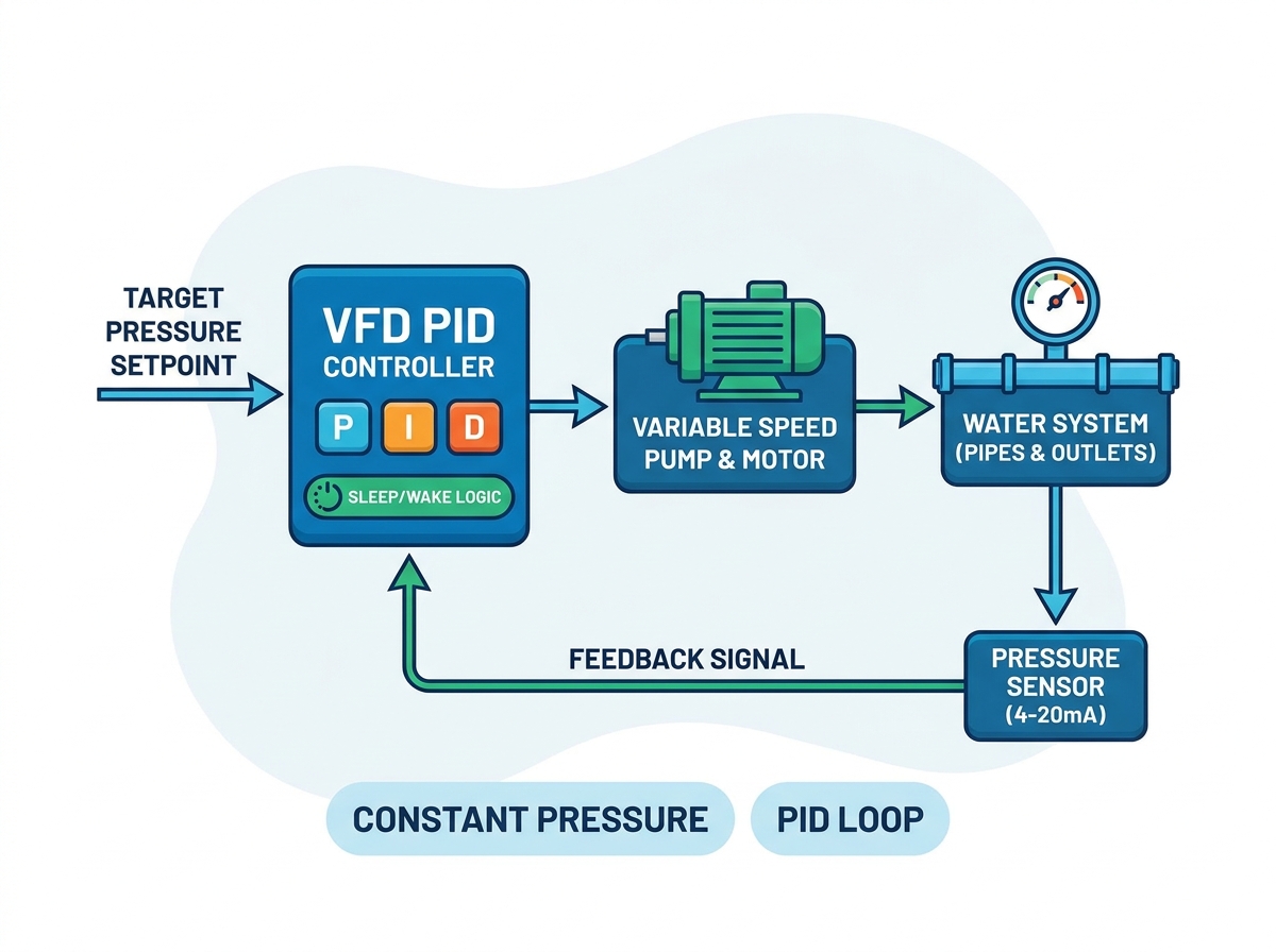
Integrating a drive into a pumping network is just the beginning of your journey. Maintaining stable water pressure across highly variable demand curves relies entirely on precise parameter configuration. The operational reality demands continuous stability, regardless of how often valves open or close. Incorrect configurations carry severe consequences. Misaligned parameters frequently lead to catastrophic pipe bursts, damaging cavitation, and premature motor failure.
Furthermore, careless setups inflate utility bills through wasted energy and frequent maintenance cycles. You cannot afford to leave your system running on factory default settings. This definitive guide will walk you through exactly how to configure your sensors, system setpoints, and critical sleep functions. You will learn proven techniques to prevent unnecessary pump wear and completely eliminate frustrating pressure oscillations.
We will provide actionable strategies to optimize your energy efficiency. Following these guidelines ensures your constant-pressure system runs flawlessly. Careful calibration ultimately maximizes long-term reliability and safeguards your critical infrastructure.
Key Takeaways
The effectiveness of a constant-pressure system depends on accurately tuning the PID control algorithm to match system dynamics.
Sensor scaling and clean feedback signals (typically 4-20mA) are non-negotiable prerequisites for stable setpoint tracking.
Properly configured sleep and wake parameters drastically reduce mechanical wear during low-demand or zero-flow periods.
Selecting a dedicated vector frequency inverter provides the necessary low-speed torque control and built-in pump macros for streamlined commissioning.
The Business and Operational Cost of Poor Pump Control
Mechanical Stress and Short-Cycling
Improperly tuned controls create immense mechanical stress. Rapid start and stop cycles wreck motor insulation over time. These harsh transitions severely degrade internal contactors. Furthermore, pump impellers suffer physical degradation from continuous abrupt force changes. Mechanical wear accelerates exponentially when systems short-cycle. You face premature equipment breakdowns and expensive emergency repairs. Stabilizing these cycles preserves your hardware and extends its operational lifespan.
Pressure Instability ("Hunting")
Aggressive parameter settings force systems to overcompensate continually. The pump overshoots the target pressure, then rapidly undershoots it. Engineers call this erratic behavior "hunting." This constant oscillation creates severe pressure instability across your piping network. Users experience fluctuating water delivery, prompting immediate complaints. More dangerously, hunting causes intense pipe fatigue. The cyclical stress fractures joints and bursts vulnerable seals over time.
Energy Waste at Zero Flow
Failing to configure sleep functions properly drains your budget. Running a pump at minimum frequency against a closed valve wastes significant energy. The motor spins continuously but produces zero flow. This scenario turns electrical power directly into useless heat. Misconfigured controls bypass vital energy-saving opportunities. Enabling strict zero-flow detection prevents this financial drain entirely. You optimize utility costs while protecting the motor from thermal damage.
Common Pump Control Failure Modes
Failure Mode
Primary Cause
Operational Impact
Short-Cycling
Narrow wake/sleep bands
Contactor burnout, motor wear
Hunting
Aggressive tuning parameters
Pipe fatigue, unstable delivery
Overheating
Running against dead head
Thermal tripping, wasted power
Applying the PID Control Algorithm to Pumping Systems
Understanding Proportional (P) Gain in Water Systems
Properly tuning the PID control algorithm guarantees your pump responds accurately. The Proportional (P) gain dictates the immediate reaction speed to a pressure drop. When pressure falls, P-gain determines how aggressively the motor accelerates. High P-gain creates a massive speed boost. However, setting this value too high introduces severe implementation risks. The system reacts violently to minor changes. This aggressive response causes massive pressure spikes and damages downstream equipment.
The Role of Integral (I) Time
Integral (I) time addresses the steady-state error remaining after the proportional response. It slowly nudges the pump speed until it matches the exact target setpoint. A properly set I-time smooths out the system response beautifully. For sluggish water systems, a longer I-time is generally safer. Slower integration prevents erratic speed changes. It gives the physical water flow time to catch up to the electronic command. This deliberate pacing completely prevents persistent oscillation.
Why Derivative (D) is Usually Disabled
The Derivative (D) function reacts strictly to the rate of change. In water distribution, pressure changes happen rapidly and irregularly. Activating the D-term often amplifies system noise. This amplified response triggers destructive water hammer events. Sudden valve closures send shockwaves through the pipes. The D-term misinterprets these shockwaves as massive demand shifts. We strongly advise leaving the Derivative parameter at zero for most constant-pressure applications.
Sensor Integration and Setpoint Calibration
Transducer Selection and Wiring Basics
Choosing the correct sensor ensures reliable data transmission. We always recommend 4-20mA transducers over 0-10V alternatives for industrial environments. Current-based signals offer superior noise immunity across long cable runs. Voltage signals degrade over distance, causing inaccurate feedback. Proper wiring techniques are equally crucial. You must use high-quality shielded cables to block electromagnetic interference. Always ground the shield at the frequency inverter side only. Grounding both ends creates ground loops, which completely corrupt the sensor signal.
Parameter Scaling (Matching Sensor to Drive)
Your drive relies entirely on accurate mathematical scaling. The transducer’s physical measuring range must perfectly align with the internal scaling parameters. Consider these essential setup steps:
Identify the transducer’s maximum rating (e.g., 0-10 Bar).
Set the drive's minimum feedback value to represent exactly 0 Bar.
Set the drive's maximum feedback value to represent exactly 10 Bar.
Verify the displayed pressure matches a physical mechanical gauge.
A mismatch here is dangerous. It represents the most common cause of drives failing to reach target pressure. Conversely, misaligned scaling can cause aggressive, dangerous overshooting.
Establishing the Target Setpoint
Setting a realistic target pressure requires careful evaluation of your physical network. Never default to maxing out the system capacity. Instead, calculate the actual demand at the highest delivery point. Then, subtract dynamic friction losses across the piping network. This calculated figure represents your true required setpoint. Over-pressurizing the system causes excessive wear on plumbing fixtures. It also forces the pump to work harder than necessary. A realistic setpoint balances reliable delivery and long-term mechanical health.
Configuring Sleep and Wake Parameters for System Longevity
Defining the Sleep Frequency Threshold
The sleep frequency threshold determines when the drive shuts down during zero demand. First, you must find the "dead head" frequency. This is the exact hertz level where the pump spins but generates zero flow. To find it, slowly close the main discharge valve. Watch the pressure gauge and motor speed. Note the frequency required to maintain target pressure at zero flow. Your final sleep frequency should sit roughly 1-2 Hz above this dead head point. This ensures prompt shutdown when demand ceases.
Sleep Delay Time
A properly configured sleep delay timer prevents nuisance tripping. Water systems frequently experience momentary, minor pressure fluctuations. A toilet flushing or a brief tap opening causes tiny drops in line pressure. If the drive reacts instantly to zero flow, it will shut down prematurely. You should configure a delay timer between 10 to 30 seconds. The drive will only enter sleep mode if zero flow persists beyond this delay. This stabilization buffer greatly reduces unnecessary on/off cycles.
Wake-Up Deviation (Wake Level)
The wake-up deviation establishes your restart threshold. This parameter tells the drive exactly when to wake up. For example, if your target is 5.0 Bar, you might set a 0.5 Bar deviation. The pump will sleep until system pressure falls to 4.5 Bar. You face a distinct operational tradeoff here. A tighter wake level maintains stricter system pressure but drastically increases start/stop frequency. A wider gap saves energy and reduces wear but causes noticeable pressure dips before the pump kicks in.
Wake-Up Strategy Comparison
Deviation Setting
Pressure Stability
Energy Efficiency
Best Application Use Case
Tight (< 0.2 Bar)
Extremely High
Low (Frequent starts)
Critical industrial processes
Moderate (0.5 Bar)
Acceptable
Good
Commercial HVAC/Plumbing
Wide (> 1.0 Bar)
Noticeable Fluctuations
Excellent
Agricultural irrigation systems
Evaluating and Shortlisting a Vector Frequency Inverter for Pumping
Application-Specific Macros vs. General Purpose Drives
Modern pumping installations benefit massively from specialized firmware. When evaluating equipment, look for drives featuring dedicated "PID/Water Supply" macros. These specialized macros pre-populate up to 80% of the necessary parameters automatically. They configure baseline PID limits, assign analog inputs, and enable sleep functions instantly. Using application-specific firmware drastically reduces commissioning time. It eliminates the tedious process of cross-referencing hundreds of generic parameters. General-purpose drives require extensive manual programming, which increases the likelihood of human error.
Sensorless Vector vs. V/F Control
Selecting a dedicated vector frequency inverter drastically improves system performance. Basic Volts/Hertz (V/F) control struggles at low motor speeds. V/F drives often stall or stutter when operating near the sleep threshold. In contrast, sensorless vector control provides superior torque response across the entire speed range. It ensures the pump can overcome initial static inertia smoothly. Furthermore, vector control maintains absolute rotational stability at very low frequencies. This stability prevents stalling before the sleep timer fully engages.
Built-In Protection Features
Your chosen drive must act as the primary defense for your pump. Ensure the selected model includes robust built-in protection features. Essential protections include dry-pump detection, which stops the motor if source water disappears. High and low-pressure alarms alert operators to pipe bursts or blockages. Advanced broken-pipe detection shuts down the system if pressure drops rapidly despite maximum motor speed. Having these features built directly into the drive eliminates the need for complex external PLCs.
Next Steps for Procurement
Thorough preparation ensures a successful hardware upgrade. You should immediately audit your current pump motor specifications. Document the full-load amps, voltage, and expected operating environment. Determine necessary IP rating requirements based on dust and moisture exposure. Additionally, inspect your existing transducer types to guarantee compatibility. Gathering these specific details before finalizing a purchase prevents costly integration delays.
Conclusion
Stable constant-pressure pumping remains a careful intersection of correct hardware selection and disciplined parameter tuning. Ignoring system dynamics leads directly to mechanical failure and wasted energy. Implementing precise PID adjustments completely eliminates erratic pressure hunting. Proper sensor scaling ensures your drive always knows the true system state.
Optimizing your sleep and wake functions yields measurable operational benefits. You will experience reduced maintenance calls, greatly extended equipment life, and predictable utility bills. We highly recommend consulting an application engineer to review your existing system architecture. Taking action today prevents catastrophic pipe failures and secures your operational reliability for years to come.
FAQ
Q: Why is my pump pressure constantly oscillating (hunting)?
A: Hunting typically occurs when the Proportional (P) gain is set too high. The system reacts too aggressively to minor pressure drops. Additionally, if the Integral (I) time is too short, it fails to smooth the response. Electrical noise on the sensor feedback line can also cause erratic readings, forcing the drive to constantly adjust speed.
Q: Should PID control be direct-acting or reverse-acting for a standard booster pump?
A: Standard booster pumps always require direct-acting PID control. In a direct-acting configuration, if the measured pressure drops below the setpoint, the motor speed increases to compensate. Reverse-acting PID is generally reserved for specific cooling tower or level-drawdown applications.
Q: Can I run multiple pumps on a single frequency inverter?
A: Yes, you can use multi-pump sequencing (cascading). One drive controls the lead pump's speed while operating staging contactors to turn auxiliary pumps on or off across the line. However, this specific setup requires a drive equipped with advanced pump control firmware and built-in relay outputs.
Q: How do I determine the correct sleep frequency for my system?
A: Perform a practical dead-head test. Slowly close the main discharge valve completely while monitoring the motor frequency and pipe pressure. The exact frequency required to maintain your target pressure at zero flow is your dead-head point. Set your baseline sleep frequency 1 to 2 Hz above this value.