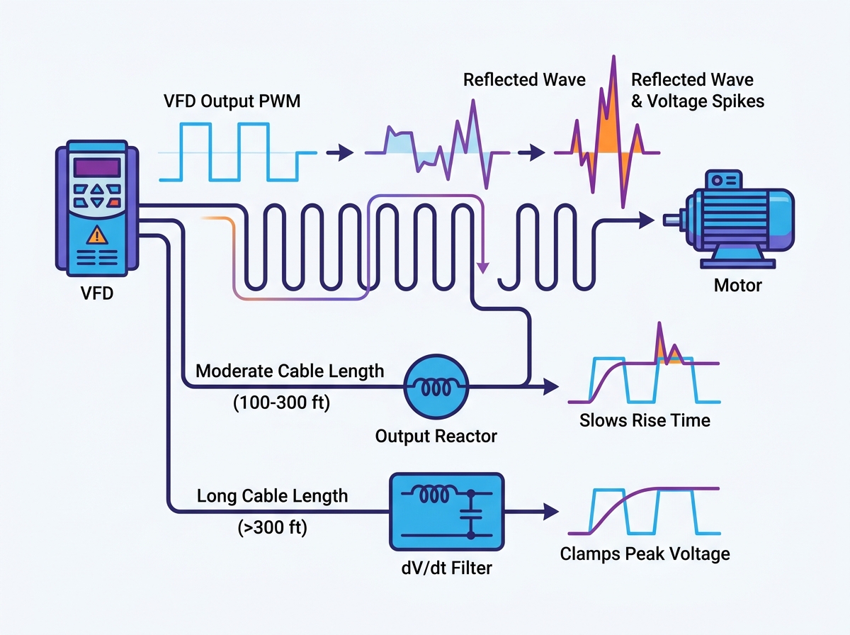
Modern industrial operations rely heavily on variable frequency drives for precise motor control. However, the fast switching speeds of today’s Insulated-Gate Bipolar Transistors (IGBTs) create incredibly steep voltage pulses. When these pulses travel over long motor cables, they reflect and compound. This creates massive voltage spikes.
These high-voltage transients rapidly degrade motor insulation. They inevitably lead to premature failure. Unplanned downtime, frequent motor rewinds, and voided warranties cost facilities significantly more than the price of upfront mitigation. You cannot afford to ignore this phenomenon when designing your motor control systems.
This article provides a clear, engineering-backed decision framework. We will evaluate exactly when an application requires an output reactor, a dV/dt filter, or a sine wave filter. You will learn how to balance real-world implementation risks, spatial constraints, and system reliability without over-engineering your solution.
Key Takeaways
Distance dictates the solution: Output reactors generally suffice for moderate cable runs (typically 100 to 300 feet), while dV/dt or sine wave filters are required for runs exceeding 300 feet.
Motor insulation matters: Non-inverter-duty motors (those not meeting NEMA MG-1 Part 31) require aggressive filtering at much shorter cable lengths.
VFD-rated cable is not a standalone fix: High-quality cable mitigates EMI and capacitive coupling but does not eliminate reflected wave voltage spikes at the motor terminals.
Implementation requires tradeoffs: Adding output mitigation components introduces voltage drops, heat generation, and spatial constraints inside the control panel.
The Physics of the Problem: Reflected Wave Damage and Cable Thresholds
To protect your equipment, you must first understand the physics driving the damage. Modern drives use Pulse Width Modulation (PWM) to control motor speed. The VFD generates a simulated AC waveform by rapidly turning DC voltage on and off. These transitions happen in fractions of a microsecond.
The Mechanism of Reflected Waves
When a PWM voltage pulse travels down a motor cable, it encounters an impedance mismatch. The cable has a specific characteristic impedance. The motor stator has a much higher impedance. When the high-speed pulse hits this boundary, a portion of the energy reflects back toward the drive. The incident wave and the reflected wave collide. They compound to create a voltage peak much higher than the original DC bus voltage.
Critical Cable Length
We define critical cable length as the threshold where reflected waves become dangerous. It occurs when the time it takes the voltage pulse to travel down the cable exceeds the rise time of the IGBTs. Today’s drives have extremely fast rise times. Therefore, critical cable lengths have become much shorter. A setup might experience severe overvoltage at just 50 feet if you use older standard-efficiency motors.
Symptoms of Unmitigated Voltage Spikes
Engineers often notice physical symptoms before catastrophic failure occurs. Look for these warning signs in your facility:
Audible noise: You might hear a distinct crackling sound. This indicates corona discharge inside the motor peckerhead.
Ozone smell: Corona discharge ionizes the surrounding air. It creates a noticeable ozone scent near the motor terminals.
Pitting on motor bearings: Common-mode voltage often accompanies reflected waves. It induces shaft currents. These currents arc through the bearings, causing frosting and pitting.
Catastrophic winding insulation failure: Continual bombardment weakens the dielectric strength of the insulation. This eventually causes phase-to-phase or phase-to-ground shorts.
Common Mistake: Many technicians replace a failed motor without investigating the root cause. If you do not address the long cable run, the replacement motor will suffer the exact same fate.
Output Reactors vs. dV/dt Filters: Evaluating the Solutions
You have three primary options for mitigating reflected wave phenomena. Each technology targets a specific range of cable lengths and operational demands. We summarize the differences in the comparison chart below.
Output Protection Strategies Comparison
Protection Type
Typical Cable Length
Primary Function
Relative Cost
Output Reactor
100 – 300 feet
Slows voltage rise time (dV/dt)
Low
dV/dt Filter
300 – 1,000 feet
Slows rise time AND clamps peak voltage
Medium
Sine Wave Filter
1,000+ feet
Converts PWM to smooth sinusoidal wave
High
Output (Load) Reactors
Output reactors are simple but highly effective components. They consist of copper or aluminum coils wound around a magnetic core. They sit between the drive and the motor.
How They Work: Reactors add inductive impedance to the output circuit. This inductance physically slows down the rise time of the voltage pulse. By reducing the rate of voltage change (dV/dt), the reactor limits the high-frequency ringing at the motor terminals.
Success Criteria: They offer cost-effective protection for moderate cable lengths. We typically recommend them for runs between 100 and 300 feet. Your exact limit depends on the carrier frequency and motor rating.
Limitations: An output reactor does not strictly cap the peak voltage. It merely slows the voltage rise time. If the cable is exceptionally long, the pulse still has enough time to reach its destructive peak. Therefore, reactors remain ineffective for ultra-long cable runs.
dV/dt Filters
When cable lengths exceed 300 feet, standard reactors lose their effectiveness. You must step up to a dV/dt filter.
How They Work: These units combine a standard reactor with a resistor-capacitor (RC) snubber circuit. The reactor slows the pulse. The RC circuit then absorbs the excess high-frequency energy. This significantly slows the rise time and actively clamps peak voltage spikes. They typically keep spikes well below 1,000V for a standard 480V system.
Success Criteria: They are ideal for cable lengths up to 1,000 feet. They also excel when retrofitting older motors. Legacy motors possess weaker insulation systems, making the RC clamping action essential.
Limitations: They require a higher upfront investment. They also occupy a larger physical footprint inside your panel. Furthermore, the snubber resistors generate substantial heat during operation.
Sine Wave Filters (For Extreme Cases)
Some applications push physical boundaries. Sine wave filters represent the ultimate tier of motor protection.
How They Work: They utilize an advanced low-pass LC (inductor-capacitor) filter design. This circuit completely strips the high-frequency PWM switching from the output. It converts the harsh square wave back into a near-perfect sinusoidal waveform.
Success Criteria: You require them for highly specific edge cases. These include lead lengths stretching over 1,500 feet. They also protect systems utilizing step-up transformers, deeply installed submersible pumps, or highly sensitive legacy motors.
Decision Framework: Choosing the Right Protection for Your Application
Selecting the correct component prevents both equipment failure and unnecessary spending. Follow this structured approach to specify your protection accurately.
Step 1: Audit the Motor Insulation. First, determine if the motor is rated for inverter duty. Check the nameplate. Motors built to NEMA MG-1 Part 31 standards feature robust insulation. They often boast a 1,600V peak insulation rating. They can withstand longer unmitigated cable runs than standard efficiency motors.
Step 2: Measure the True Cable Path. Never rely on point-to-point line of sight. Cables weave through trays, drop down walls, and snake around machinery. You must measure the actual routed cable length. A visual 100-foot gap often requires 250 feet of routed cable.
Step 3: Consult VFD Hardware Specifications. Different drives possess distinct switching characteristics. Reviewing the specific VFD installation instructions is critical. For example, when commissioning an SD300 frequency inverter, you must identify factory-recommended maximum lengths. Manufacturers list strict guidelines for both unshielded and shielded cables before external filtering is mandated.
Step 4: Factor in the Carrier Frequency. Drive settings change physical realities. Higher carrier frequencies (e.g., 8kHz versus 2kHz) exacerbate reflected waves. Faster switching means more pulses per second. This generates more heat in filter components and accelerates insulation degradation. You may need to derate the drive or size up the filter accordingly.
Best Practice: Always document your findings during the audit phase. Create a simple spreadsheet tracking motor location, routed cable length, nameplate data, and programmed carrier frequency.
The Role of VFD-Rated Cable in the Protection Matrix
Engineers often debate cable types during installation planning. A dangerous misconception exists regarding mitigation devices and cable selection.
Addressing the Misconception
Many installers believe that installing an output reactor or filter eliminates the need for proper VFD cable. They assume standard THHN wire in a conduit will suffice once the voltage spikes are capped. This assumption introduces severe operational risks.
Why VFD Cable is Still Necessary
Filters and cables perform completely different jobs. Filters protect the motor from damaging voltage spikes. However, shielded cables protect the facility from Electromagnetic Interference (EMI). Standard cables leak high-frequency noise into the surrounding environment. This noise easily disrupts sensitive sensors, PLCs, and communication networks.
Furthermore, VFD-rated cables safely manage high-frequency ground currents. They utilize symmetric ground wires to provide a low-impedance path back to the drive. This prevents destructive stray currents from finding alternative paths through building steel or machinery bearings.
Synergy
You achieve the highest-reliability installation through synergy. Combine an appropriate output filter with symmetric ground VFD cable. The filter manages the voltage stresses at the motor terminals. The cable contains the electrical noise and manages the ground currents safely. Together, they create a robust, interference-free motor control system.
Implementation Realities and Hidden Costs
Adding components to your electrical panels introduces new engineering challenges. You must account for these realities before finalizing your design.
Voltage Drop and Torque Reduction
Reactors and filters add impedance to the circuit. This naturally induces a voltage drop, typically between 3% and 5%. If your motor operates near its maximum capacity, this drop becomes problematic. The motor receives less voltage, which directly reduces its available torque. You must evaluate if the motor requires a slightly higher input voltage from the drive to maintain full load torque.
Panel Space and Thermal Management
Physical constraints often dictate engineering choices. dV/dt and sine wave filters are bulky. You cannot simply squeeze them into a crowded panel. Furthermore, they generate heat. The resistors inside a dV/dt filter dissipate excess energy as thermal load. You must calculate the additional BTU heat load. Failing to do so causes enclosure overheating, which leads to nuisance tripping and premature component failure. Ensure your cooling fans or enclosure air conditioners can handle the extra watts.
Compliance and Short-Circuit Ratings
Safety regulations demand careful component selection. Ensure your chosen reactors and filters align with UL508A enclosure requirements. You must also verify the facility SCCR (Short-Circuit Current Rating) standards. Adding a mismatched component can lower the entire panel's safety rating, causing compliance failures during inspections.
Conclusion
Protecting your motors from reflected wave damage requires a clear understanding of system physics and hardware capabilities. There is no universal "best" filter. Your decision hinges strictly on exact cable distance, motor insulation age, and specific budget constraints.
We recommend taking immediate, actionable steps to secure your systems. First, task your engineering team to document all cable lengths exceeding 100 feet. Second, cross-reference these lengths with drive manuals and motor nameplates. Finally, audit your current risk profile. Implement output reactors for moderate runs and step up to dV/dt or sine wave filters when distances or older motors demand aggressive mitigation.
FAQ
Q: If I install a dV/dt filter, do I still need to use VFD-rated cable?
A: Yes. A filter mitigates motor overvoltage, but VFD cable contains EMI, reduces capacitive coupling, and safely manages high-frequency noise. They perform distinct, complementary functions. Skipping the shielded cable exposes your facility networks to severe communication disruptions.
Q: Can I run multiple motors off a single VFD with long cables?
A: Yes, but the total capacitive cable length must be calculated. You must sum all branch lengths together. Use this combined total distance to size the output reactor or filter correctly. Ignoring branch lengths will lead to an undersized filter and inadequate protection.
Q: Do I need an output reactor if I already have a line reactor on the input?
A: Yes. They serve entirely different purposes. A line reactor sits on the input side to protect the drive from power grid transients and harmonic distortion. An output reactor sits on the load side to protect the motor from drive-generated transients.
Q: How does carrier frequency affect the choice of output filter?
A: Higher carrier frequencies increase the number of voltage pulses per second. This generates significantly more heat in filter capacitors and resistors. The filter must be specifically rated for your programmed carrier frequency to prevent catastrophic overheating and component failure.