
Views: 0 Author: Site Editor Publish Time: 2026-09-08 Origin: Site


Aging elevator infrastructure forces facility managers and contractors to balance modernization budgets against strict performance and safety standards. Selecting the right drive technology dictates the success of a modernization project. Specifying a closed-loop system when unnecessary inflates budgets and complicates installation. Conversely, under-specifying an open-loop system can lead to poor ride quality, elevator rollback, and code compliance failures. You must match the drive capabilities to the mechanical realities of the existing hoistway. We will establish a technical framework for evaluating whether an open-loop architecture can meet the specific load, speed, and leveling requirements of your building's modernization project without compromising safety, equipment longevity, or user experience.
Application Limits: Open-loop systems are highly viable for low-speed, low-rise, and freight applications where millimeter-perfect stopping accuracy is secondary to reliable, cost-effective operation.
Technical Trade-offs: The absence of encoder feedback reduces hardware complexity and installation time but requires precise initial tuning to mitigate load-variant issues like elevator rollback.
Equipment Safeguards: Modern open-loop drives come equipped with robust protection features that actively shield aging legacy motors from power anomalies.
Cost vs. Performance: Opting for an open loop elevator drive significantly reduces upfront component and labor costs, making it a strategic choice for budget-constrained retrofits on legacy geared traction machines.
Risk Mitigation: Successful deployment relies on pairing the inverter with robust external leveling sensors and ensuring compatibility with existing legacy controllers.
When modernizing an aging traction elevator, the existing motor often dictates the electrical upgrades. A legacy AC motor designed for line-starting across the contactors experiences massive inrush currents. This degrades winding insulation over decades of use. Integrating an Open Loop Elevator Inverter replaces the harsh mechanical contactor logic with precise solid-state control. The drive converts incoming alternating current into a direct current bus voltage, then uses insulated-gate bipolar transistors to pulse-width modulate a new AC waveform. This allows you to dictate the exact frequency and voltage applied to the motor stator.
Sensorless vector control relies on complex motor modeling. The drive microprocessor continuously monitors the output current and voltage. By measuring the back-electromotive force returning from the motor, the drive calculates the rotor's slip and estimates its physical position. You do not need a physical encoder mounted to the motor shaft. This mathematical modeling allows the drive to adjust the output dynamically to maintain the commanded speed under varying load conditions.
Control Method |
Feedback Mechanism |
Torque Control at Low Speed |
Typical Application |
|---|---|---|---|
Volts-per-Hertz (V/f) |
None (Fixed Ratio) |
Poor |
Basic Material Lifts |
Sensorless Vector |
Back-EMF Calculation |
Good |
Passenger & Freight Modernizations |
Closed Loop Vector |
Physical Encoder |
Excellent |
High-Speed Gearless Systems |
Removing the encoder requirement fundamentally simplifies hoistway wiring. Encoders require shielded, twisted-pair wiring to transmit high-frequency pulse signals back to the controller. In a modernization, pulling a new traveling cable just to accommodate encoder wiring adds days of labor and significant material expense. You also eliminate the mechanical frustration of machining an old motor shaft to accept an encoder mounting bracket. This reduction in physical components streamlines the entire installation process.
Legacy motors are highly susceptible to power anomalies. Modern drives include built-in electrical safeguards that monitor incoming power quality. They provide immediate overvoltage, overcurrent, and phase loss protection. If the building experiences a brownout or a dropped phase, the inverter faults safely and drops the mechanical brake. This prevents the motor windings from absorbing the electrical fault and burning out.
Certain modernization projects face strict building power constraints. Older residential buildings or light commercial structures often lack access to three-phase power in the machine room. Upgrading the building's electrical service is usually cost-prohibitive. In these scenarios, specifying a single phase elevator drive solves the infrastructure problem. These specialized drives accept a standard single-phase input and utilize their internal DC bus to generate a true three-phase output. This allows you to run standard three-phase elevator motors without rewiring the building's main electrical feed.
Before ordering hardware, you must establish clear success criteria based on the building's lifecycle. Assess whether the facility requires a short-term 10-to-15-year life extension or a complete 30-year architectural overhaul. A short-term life extension heavily favors open-loop modernization. You retain the existing geared machine and simply upgrade the control panel and drive. A massive 30-year overhaul might justify the labor and expense of a full machine replacement, moving to a gearless permanent magnet motor that requires closed-loop control.
Passengers expect specific comfort levels regardless of the drive technology hidden in the machine room. You must define the non-negotiable outcomes for the modernization. Key metrics include jerk rates, acceleration profiles, and acoustic noise reduction. The system must deliver stable control performance from floor to floor. A successful open-loop installation will completely eliminate the harsh, jarring starts and stops typical of legacy two-speed or line-started relay systems.
Elevator safety codes strictly govern modernization projects. You must adhere to local jurisdictional standards, typically based on ASME A17.1 or CSA B44. These codes dictate specific requirements regarding unintended car movement protection. The inverter must interface directly with the elevator controller's safety string and the emergency braking system. If the car drifts away from the floor with the doors open, the system must detect the movement, drop the contactors, and apply the brake immediately.
The chosen inverter directly impacts the mechanical wear and tear on legacy components. Harsh motor starts degrade traction ropes, wear down sheave grooves, and stress worm gearboxes. By implementing controlled, S-curve torque ramps, an open-loop drive extends the operational life of these expensive mechanical parts. You reduce the frequency of rope shortenings and replacements. You also limit the structural fatigue applied to the machine bedplate and deflector sheaves.
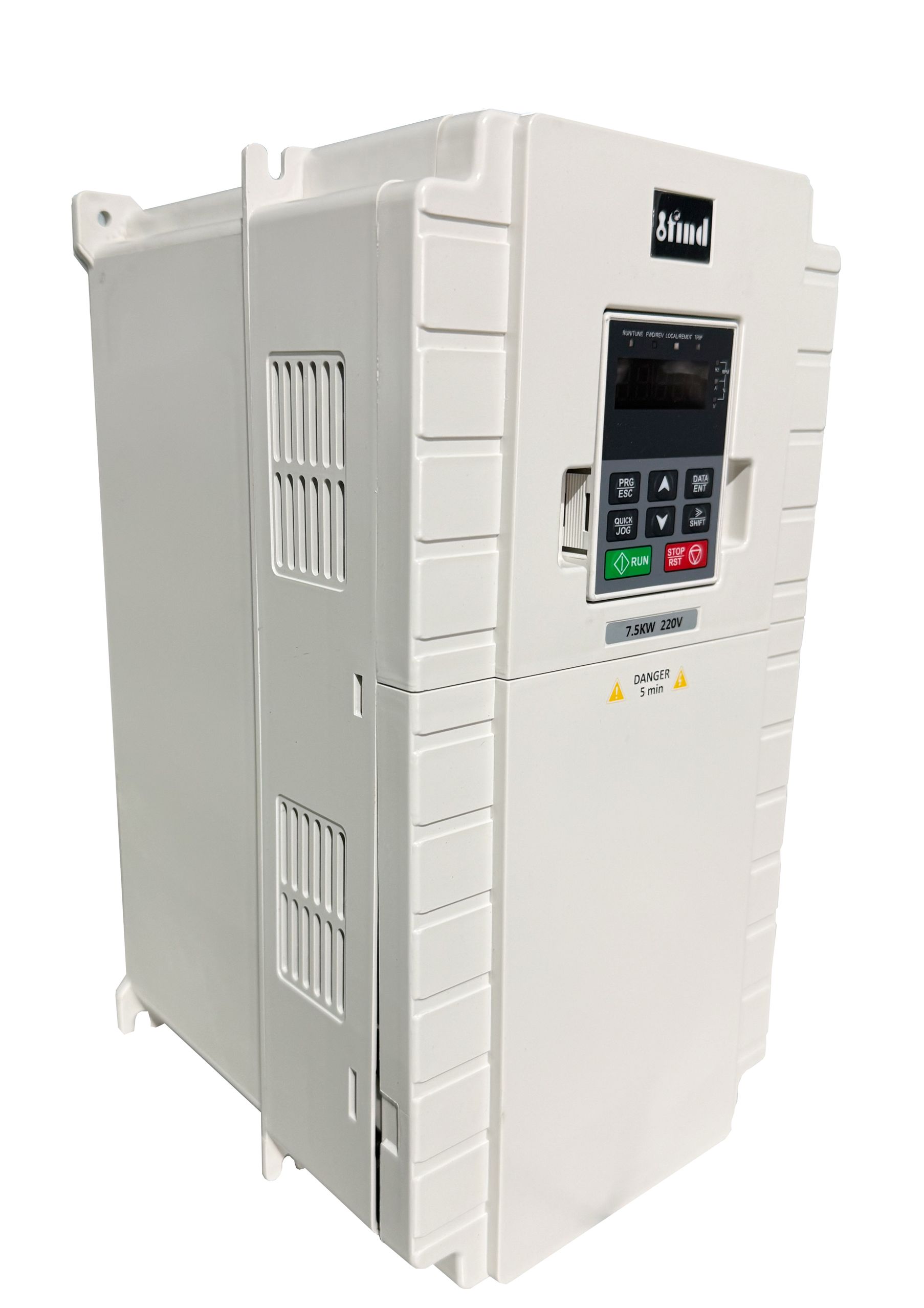
Torque response times differ fundamentally between open-loop and closed-loop systems. Closed-loop drives use direct encoder feedback to adjust torque in milliseconds, providing absolute control at zero speed. Open-loop systems rely on sensorless vector control, which has a slightly slower torque response time because it must calculate the rotor position based on electrical feedback. However, modern microprocessors process these calculations fast enough to close this performance gap for most standard applications.
Sensorless vector control impacts passenger comfort primarily during the start and stop phases. Without an encoder, the drive must build magnetic flux in the motor stator before commanding the brake to lift. If you tune the start parameters incorrectly, this flux build-up can cause a slight vibration in the car. When you calibrate the start profile properly, the transition is smooth. Open-loop performance becomes indistinguishable from closed-loop to the average passenger at speed thresholds typically under 1.5 meters per second.
Elevator rollback occurs when the car moves slightly against the intended direction just as the brake lifts. This happens due to load imbalances between the car and the counterweight. If the motor does not generate sufficient holding torque before the brake fully opens, gravity pulls the heavier side downward. This is a common failure point in poorly tuned modernizations.
An open loop lift inverter handles pre-torque requirements without direct position feedback by utilizing advanced software algorithms. Since it cannot read exact motor shaft movement, it relies on DC injection braking. The drive injects direct current into the motor windings to magnetically lock the rotor in place while the mechanical brake lifts. Once the brake is fully clear, the drive transitions to standard AC frequency output to move the car.
You must set realistic performance expectations based on the existing machinery. Software-level mitigation features in open-loop drives are highly effective for geared traction machines. The worm gear inherently resists rollback due to its mechanical friction. The gear reduction acts as a natural holding force. This contrasts with gearless machines, which have almost no mechanical friction and require the hardware-based precision of closed-loop systems to hold the motor perfectly still at zero speed.
Open-loop systems rely entirely on external hoistway sensors for floor leveling. Magnetic switches, optical sensors, or physical vanes mounted in the shaft tell the controller when to initiate deceleration and when to apply the brake. The drive itself does not know the car's exact position in the hoistway; it only executes the speed commands sent by the controller based on those sensor inputs.
Performance Metric |
Open Loop Architecture |
Closed Loop Architecture |
|---|---|---|
Stopping Tolerance |
±10mm to ±15mm |
±1mm to ±3mm |
Position Feedback |
Hoistway Vanes / Magnetic Switches |
Motor Shaft Encoder |
Zero-Speed Holding |
DC Injection Braking |
Absolute Torque Control |
Ideal Machine Type |
Geared Traction |
Gearless Permanent Magnet |
Maximum Recommended Speed |
1.5 m/s |
Unlimited |
You must determine acceptable stopping limits for different building types. A stopping tolerance of ±10mm is perfectly acceptable for standard residential buildings, apartment complexes, or warehouses. The slight variation is unnoticeable to foot traffic. However, hospitals moving wheeled stretchers or laboratories transporting sensitive equipment require the ±3mm precision that only a closed-loop system can guarantee to prevent tripping hazards at the threshold.
You can confidently specify open-loop drives in buildings under 7 stories with elevator speeds below 1.5 m/s. These applications do not require the extreme high-speed control loops necessary for high-rise skyscrapers. The travel distances are short, and the acceleration profiles are relatively simple. The mechanical demands on the system fall perfectly within the capabilities of sensorless vector control.
These low-rise structures commonly utilize older, geared traction machines. The mechanical reduction of the gearbox provides inherent stability. An open loop elevator drive pairs perfectly with these geared machines. The drive modernizes the electrical control, eliminates the harsh contactor logic, and leverages the mechanical advantages of the existing worm gear to provide a smooth, reliable ride.
Absolute ride smoothness is less critical than high starting torque and durability in freight applications. Freight elevators transport heavy, static loads. The primary goal is reliable vertical transport under extreme weight variations. Open-loop drives excel at delivering raw torque to move heavy materials. They handle the massive current demands required to lift fully loaded freight cars without faulting.
Removing delicate encoders provides a massive advantage in harsh, industrial environments. Dust, debris, and extreme vibration in factories or warehouses cause frequent optical encoder failures. Forklifts driving onto the platform cause massive suspension bounce, which sends shockwaves up the hoistway ropes directly into the motor shaft. This shock destroys encoder glass disks. By eliminating the encoder, you ensure stable control performance and drastically reduce maintenance callouts.
Many building owners face scenarios where full machine replacement or closed-loop modernization is financially unviable. Condominium boards or small commercial property owners often operate with strict capital limits. Upgrading to a closed-loop system requires buying a new motor or paying a machine shop to bore out the old motor shaft to accept an encoder. This adds thousands of dollars and weeks of delay to the project.
Open-loop systems extend the lifecycle of existing mechanicals with minimal electrical overhaul. You replace the aging relay-logic controller and line-starter with a modern microprocessor controller and an open-loop drive. This upgrades the safety and reliability of the elevator, improves floor leveling, and keeps the project within a tight budget. You maximize the value of the existing heavy iron in the machine room.
Empty cars and fully loaded cars will decelerate differently without encoder feedback. Gravity assists a heavy car moving downward, causing it to slide slightly further after the brake drops. An empty car moving downward will stop more abruptly because the heavy counterweight is pulling against it. This load variance can cause inconsistent floor leveling if the drive is not tuned correctly.
To mitigate this, you must implement multi-speed deceleration profiles within the drive parameters. You must also ensure precise calibration of the hoistway leveling switches.
Conduct a full-load test to measure the maximum downward slide distance.
Adjust the deceleration distance parameter in the drive to initiate the slowdown earlier.
Optimize the brake drop timing so the mechanical brake applies exactly as the motor reaches zero speed.
Fine-tune the DC injection braking voltage to hold the car steady during the brake transition.
Open-loop drives can struggle to maintain high torque at very low frequencies. To generate enough torque to hold the load during the final leveling approach, the drive must push higher current into the motor stator. This increased current at low speeds generates significant heat. Legacy motors rely on an internal fan attached to the rotor for cooling. At low speeds, this internal fan moves very little air, which can degrade motor insulation over time.
You mitigate this risk through proper inverter sizing and external cooling. Consider over-sizing the drive by one frame size to handle higher current demands without stressing the drive's internal components. You should also utilize forced-air motor cooling by installing an external, constant-speed blower fan on the legacy motor housing. Finally, optimize the V/f curve in the drive settings to provide an adequate torque boost without causing excessive current saturation in the windings.
Older relay-logic or early solid-state controllers lack the digital communication protocols required for modern drive handshakes. The controller must communicate run commands, speed selections, direction, and fault statuses to the drive. Incompatible signaling can prevent the system from operating safely or cause intermittent shutdowns.
You must conduct a thorough electrical audit prior to specification. Map out the existing controller's input and output capabilities. To bridge communication gaps, utilize the programmable relay outputs on the inverter. You can program these relays to mimic the contactor logic expected by the older controller. This ensures the drive and the controller remain synchronized, preventing the controller from dropping the safety string prematurely.
Audit the existing motor nameplate data and perform a megger test to assess stator winding health before specifying a drive.
Test the accuracy and physical condition of the existing hoistway leveling switches to determine if they require replacement.
Map the legacy controller's input and output capabilities to ensure compatibility with modern drive relay signaling.
Perform a comprehensive load-weighing assessment to configure accurate deceleration profiles and prevent rollback.
A: The primary function is to convert incoming power into a precisely controlled variable frequency and voltage. This regulates the speed and torque of the elevator motor, providing smooth acceleration, reducing mechanical wear on aging components, and improving overall ride quality compared to legacy line-started systems.
A: The main difference is position feedback. A closed-loop drive uses a physical encoder mounted on the motor shaft to track exact speed and position. An open-loop drive operates without an encoder, relying on internal mathematical models and electrical feedback to estimate and control motor performance.
A: Yes. While it lacks an encoder for absolute zero-speed holding, modern open-loop drives use anti-rollback software and DC injection braking. These features lock the motor magnetically for a fraction of a second while the mechanical brake lifts, preventing the car from rolling against the intended direction.
A: Yes. Single-phase open-loop drives are available for buildings lacking three-phase power. They accept a single-phase input and internally convert it to output the three-phase power required to run standard elevator motors, making them ideal for small residential or light commercial retrofits.
A: Open-loop inverters are generally recommended for elevator speeds up to 1.5 meters per second. Beyond this speed, the dynamic control requirements and strict stopping tolerances necessitate the precision of a closed-loop system with direct encoder feedback.
A: It relies entirely on external hoistway sensors, such as magnetic switches or optical vanes. When the car passes a sensor, the controller commands the drive to decelerate and eventually drop the brake. The drive executes these speed commands based on the physical sensor triggers rather than internal position tracking.
A: Yes. When properly installed and integrated with a compliant elevator controller, open-loop drives meet modern safety standards like ASME A17.1 and CSA B44. They interface safely with emergency braking systems and unintended car movement protection devices.


