Converting photons to electricity is an inherently volatile process. Cloud cover, time of day, and seasonal shifts constantly alter the energy output of a solar array. Yet, agricultural and industrial water demands require strict reliability. You cannot pause irrigation just because a cloud passes overhead. Direct-wired solar arrays without intelligent regulation experience severe voltage drops during low-light conditions. When irradiance falls, the current drops. This results in pump stalling, inconsistent water delivery, and premature motor failure due to low-voltage thermal stress. Operators facing these failures often revert to unsustainable diesel generators to maintain their water supply.
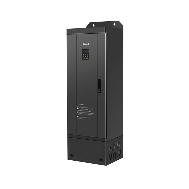
The Solar Pump Inverter serves as the critical regulatory component, acting as the system's brain. We will evaluate how these inverters manipulate variable DC input to provide stable motor control, maximize efficiency, and how to select the right hardware for specific operational criteria.
Dynamic Power Optimization: High-quality inverters utilize Maximum Power Point Tracking (MPPT) to continuously adjust electrical load, extracting the maximum available power from the solar array regardless of cloud cover.
Variable Speed Control: By adjusting the output frequency (Hz) to the motor, the inverter allows the pump to run at lower speeds during partial shading, maintaining flow rather than shutting down completely.
Motor Protection & Stability: Advanced inverters prevent equipment damage by regulating voltage, providing soft-start capabilities to reduce mechanical stress, and integrating dry-run protection.
System Compatibility: Selecting the correct inverter requires matching its phase output, voltage range, and surge capacity to the specific pump type (e.g., deep-well submersible vs. surface).
The Mechanics of Variable Sunlight on Pumping Systems
To understand the value of intelligent power regulation, we must establish the baseline requirements for reliable water pumping. A successful pumping system must maintain consistent head pressure, achieve minimum flow rates, and operate within strict motor thermal limits. Water pumps are demanding loads. They require a specific amount of torque to overcome the static head pressure of the well or pipeline. If the power supply cannot deliver that torque, the system fails to move water.
Direct connections between solar panels and pump motors represent a massive point of failure. Solar panels operate on a specific Voltage-Current (V-I) curve. Under partial shade, the current produced by the panels drops significantly. Because the motor still attempts to draw the power required to move the water column, it pulls down the system voltage. This physical reality causes a standard AC or DC motor to stall. When a motor stalls while receiving power, it acts essentially as a short circuit. It overheats rapidly, fails to overcome the static head pressure, and the internal windings begin to degrade.
The primary function of the inverter is decoupling the solar array's variable DC output from the pump's strict power requirements. It achieves this through continuous power conditioning and frequency modulation. The inverter acts as a buffer. It reads the available DC power from the panels and reconstructs it into a usable AC waveform that matches exactly what the motor can safely handle at that specific moment. By maintaining optimal voltage levels between the panels and the load, the inverter prevents thermal stress and ensures continuous operation.
Operational Condition
Direct-Wired Solar Pump
System with Intelligent Inverter
Morning / Low Irradiance
Motor stalls, draws high current, generates heat.
Inverter waits for threshold, executes soft-start at low Hz.
Passing Clouds
Voltage drops abruptly, pump stops moving water.
Inverter lowers frequency, pump slows down but maintains flow.
Peak Midday Sun
Operates normally, but wastes excess voltage.
MPPT extracts maximum power, runs pump at maximum safe RPM.
Dusk / Sunset
Motor stutters and stalls under load.
Inverter detects low DC bus voltage and enters safe sleep mode.
Field technicians frequently encounter burned-out stators in direct-wired systems. The insulation on the copper windings melts when the motor sits in a stalled state during early morning or late afternoon hours. The inverter eliminates this failure mode entirely by refusing to send power to the motor until the solar array can support the minimum required frequency to spin the impeller.
Core Technologies: How a Solar Pump Inverter Stabilizes Flow
The ability to maintain water flow under shifting weather conditions relies on two primary technologies working in tandem. The inverter must extract the maximum power available from the panels and then format that power to keep the motor spinning safely.
MPPT Technology
The Maximum Power Point Tracking (MPPT) algorithm is the foundation of solar efficiency. As cloud cover shifts, the optimal operating point of a solar array changes constantly. MPPT continuously calculates the optimal voltage-to-current ratio to maximize wattage output. It sweeps the solar array's power curve thousands of times per second. It finds the exact point on the curve where voltage and current multiply to create the highest possible power.
This ensures the energy harvested from the sun is never wasted. When evaluating hardware, you must differentiate between basic PWM (Pulse Width Modulation) controllers and true MPPT technology. A high-quality MPPT solar pump inverter typically achieves a 98-99% yield. PWM controllers simply clip the excess voltage, wasting valuable energy that could be used to move water during marginal weather conditions. In a 10kW array, a PWM controller might waste up to 3kW of potential power during suboptimal sunlight, whereas an MPPT system captures and utilizes that power to keep the pump running.
Variable Frequency Drive (VFD) Integration
Once the MPPT algorithm secures the maximum DC power, the Variable Frequency Drive (VFD) component takes over. The inverter converts the DC power to variable AC power. This is where dynamic flow stabilization occurs.
During peak sunlight hours, the inverter capitalizes on maximum irradiance. It runs the pump at its maximum safe speed, typically 50Hz or 60Hz depending on the motor nameplate, to maximize water output and fill storage tanks rapidly. This bulk water storage acts as a mechanical battery for the system, providing gravity-fed water even after the sun goes down.
The true value of the VFD emerges during low-sun conditions. As sunlight drops, the available power decreases. Instead of allowing the motor voltage to collapse and stall, the inverter utilizes V/f (Voltage/Frequency) control. It proportionally lowers both the voltage and the frequency sent to the motor. For example, it may drop the output from 60Hz to 40Hz. According to pump affinity laws, reducing the pump speed significantly reduces its power demand. The outcome is continuous, albeit reduced, water flow during cloudy periods rather than abrupt system shutdowns.
Low-Light Wake-Up and Sleep Functions
Manual intervention is impractical for remote agricultural sites. Modern inverters utilize automated threshold parameters to manage daily operational cycles. They rely on internal DC bus voltage sensors to determine when enough solar energy is available to safely spin the motor.
The inverter senses morning irradiance. Once the voltage hits a specific threshold, it initiates a soft start. This gradually ramps up the frequency, preventing massive inrush currents that could damage the motor or the mechanical pump shaft. Conversely, it automatically enters sleep mode at dusk. When the available solar power can no longer maintain the minimum frequency required to overcome static head pressure, the inverter shuts the system down gracefully. This prevents motor strain and eliminates the risk of draining any connected auxiliary systems.
Wake-up Voltage: The specific DC voltage required to initiate the soft-start sequence.
Sleep Frequency: The minimum Hz threshold where the pump can no longer move water, triggering a shutdown.
Restart Delay: A programmed timer preventing the inverter from rapidly cycling on and off during highly variable cloud cover.
Evaluating Inverter Performance Across Pump Types
Not all water pumps behave the same way under variable power conditions. The mechanical design of the pump dictates how the inverter must deliver power. You must match the inverter's control logic to the specific hydraulic realities of your water source.
Submersible Pump Requirements
Deep well applications present unique physics. Submersible pumps require high initial breakaway torque to push water up a significant vertical lift. The static head pressure is immense before the water even reaches the surface. If the motor cannot generate enough torque instantly, the impeller will not turn, and the motor will draw locked-rotor current.
When evaluating a submersible pump solar inverter, you must assess its overload capacity. It needs the ability to provide short-term current surges without tripping its internal protection circuits. Furthermore, precise low-frequency torque control is an absolute necessity. During low-sun conditions, the inverter might run the pump at 35Hz. At this low speed, the inverter must still maintain enough torque to keep the water column lifted. If it fails, the water falls back down the well, spinning the pump backward and potentially causing mechanical damage to the thrust bearings.
Pump Type
Primary Hydraulic Challenge
Critical Inverter Feature Required
Deep Well Submersible
High static head pressure, heavy vertical lift.
High starting torque, robust overload capacity (150% for 60s).
Surface Centrifugal
High volume, risk of cavitation with pressure drops.
Rapid frequency response, stable PID control loops.
Positive Displacement
Constant torque requirement regardless of speed.
Strict V/f curve management, low-speed current regulation.
Surface Pump Considerations
Surface pumps operate under different constraints. They typically handle high volumes of water at lower head pressures. You find them moving water from shallow ponds, rivers, or transfer tanks. While they do not fight massive vertical lift, they are highly susceptible to cavitation if the flow becomes inconsistent.
Cavitation occurs when rapid pressure changes create vapor bubbles inside the pump casing. These bubbles implode, destroying the brass or stainless steel impellers over time. For surface applications, you must look for inverters with rapid frequency response times. When fast-moving cloud cover causes sudden power drops, the inverter must adjust the motor speed instantly to maintain stable suction. Slow response times lead to pressure fluctuations, air intake, and severe cavitation damage.
Key Features to Evaluate in a Commercial-Grade Inverter
Beyond basic power conversion, enterprise-grade hardware includes layers of logic designed to protect the mechanical infrastructure. A burned-out pump at the bottom of a 300-foot well is a catastrophic failure. The inverter must prevent this through active monitoring and automated fault responses.
Dry-Run Protection and Sensor Integration
Running a pump without water destroys the mechanical seals and melts the impellers within minutes. Traditional systems rely on physical float switches or well probes to detect low water levels. However, physical sensors corrode, wires break, and installation adds complexity down the well casing.
Modern inverters utilize sensorless dry-run protection. The inverter constantly monitors the motor's power factor and current draw. If the well runs dry, the mechanical load on the pump drops instantly. The inverter detects this sudden drop in motor load because the current phase angle shifts. It immediately shuts down the system to prevent pump burnout. It will then wait a pre-programmed amount of time, often 30 to 60 minutes, to allow the well to recover before attempting an automatic restart.
Hybrid Power and Auto-Switching Capabilities
Some agricultural operations cannot tolerate any reduction in flow rate, regardless of the weather. For these critical applications, AC/DC blending features are mandatory. Enterprise-grade inverters automatically supplement solar drops with grid power or diesel generators.
If heavy overcast conditions reduce solar output to 40% of the pump's requirement, a hybrid inverter rectifies AC power from the grid to make up the remaining 60%. This happens on the internal DC bus without any interruption to the motor. It maintains a 100% flow rate while prioritizing free solar energy first, only drawing the exact amount of auxiliary power needed to bridge the gap. This seamless transition prevents the mechanical shock of hard starting and stopping the pump multiple times a day.
Remote Monitoring and Diagnostics (IoT)
Managing multiple pump stations across hundreds of acres requires data visibility. You cannot physically inspect every well daily. RS485 and GPRS connectivity transform an isolated pump into a managed asset.
Remote monitoring allows operators to track daily water yield, monitor DC bus voltage, and detect faults in real-time. If a pump jams due to sand ingestion, the inverter trips on overcurrent and sends an immediate alert to a mobile device. Engineers can adjust PID parameters, change wake-up thresholds, and clear faults remotely, saving hours of driving time and preventing crop loss.
Overcurrent (OC): Indicates a jammed impeller, shorted motor winding, or heavily undersized inverter.
Overvoltage (OV): Usually occurs during rapid deceleration or if the solar array is wired with too many panels in series.
Undervoltage (UV): Triggered by heavy cloud cover or degraded solar panels failing to provide minimum DC bus voltage.
Dry Run (DR): Indicates the water source has depleted and the pump is spinning freely without load.
Implementation Risks and System Sizing Realities
Even the most advanced hardware will fail if it is deployed incorrectly. System design requires strict adherence to electrical and environmental parameters. The most common failures in the field stem from poor sizing and inadequate thermal management.
Oversizing vs. Undersizing the Inverter
Matching the inverter to the motor is a delicate balance. Undersizing the inverter leads to thermal clipping. The inverter will constantly hit its current limit, overheat, and shut down to protect its internal IGBTs (Insulated-Gate Bipolar Transistors). This causes premature component failure and constant nuisance tripping. Conversely, heavily oversizing the inverter wastes capital and can cause inefficiencies at low loads, as the internal sensors may struggle to read the minute current draws of a much smaller motor.
The standard engineering rule of thumb is sizing the solar water pump inverter at 120% to 150% of the pump motor's rated power. This buffer handles the massive startup surges required by deep well pumps. It also provides a critical safety margin for high ambient temperatures. As environmental heat rises, the inverter's ability to dissipate internal heat decreases, requiring a larger capacity rating to maintain continuous output without derating.
Environmental Durability and Thermal Management
Agricultural environments are hostile to electronics. Inverters installed near fields or wells face constant bombardment from dust, moisture, insects, and extreme heat. A standard indoor drive will fail rapidly in these conditions.
You must evaluate the Ingress Protection (IP) ratings based on your installation plan. If mounting the unit directly on a pole outdoors, an IP65 or IP66 rating is non-negotiable. These enclosures are dust-tight and protected against heavy water jets. If you are installing the hardware inside a climate-controlled pump house or a sealed NEMA cabinet, an IP20 rating is sufficient.
Installation Environment
Recommended IP Rating
Cooling Mechanism
Outdoor Pole Mount (Exposed)
IP65 / IP66
Passive fanless heat sink or sealed internal fan.
Vented Pump House
IP54
Variable speed cooling fans with dust filters.
Sealed Control Cabinet
IP20
Standard active cooling, relying on cabinet ventilation.
Thermal management is equally critical. Look for passive cooling mechanisms like massive fanless heat sinks for lower-wattage units. For high-power commercial systems, variable speed cooling fans that only activate under heavy thermal loads prevent unnecessary dust intake and extend the lifespan of the cooling mechanism.
Conclusion
The solar pump inverter is far more than a simple power converter. It is the primary safeguard for motor longevity, flow reliability, and overall system efficiency under volatile weather conditions. By dynamically adjusting voltage and frequency, it ensures that your water infrastructure remains operational from sunrise to sunset, regardless of passing clouds.
When shortlisting hardware, buyers must base their final selection on exact motor specifications, including voltage and phase requirements. Calculate the specific dynamic head of the water source to ensure the inverter can handle the required starting torque. Determine the necessity for hybrid grid or generator backup based on your crop's drought tolerance.
Take the following steps to finalize your system design:
Audit your current pump motor nameplate to document the exact kW rating, voltage, and full-load amperage.
Calculate your daily water volume requirements to determine the minimum acceptable flow rate during low-light hours.
Assess your installation environment to determine if you require an IP65 outdoor enclosure or an IP20 cabinet-mounted unit.
Consult with a technical sales engineer to request detailed inverter spec sheets and confirm MPPT efficiency ratings.
FAQ
Q: What is the difference between a standard inverter and a solar pump inverter?
A: A standard inverter converts DC to fixed AC power. A solar pump inverter integrates Variable Frequency Drive (VFD) capabilities and Maximum Power Point Tracking (MPPT). It dynamically adjusts the output frequency to match available solar energy, allowing direct-to-pump operation without relying on battery banks.
Q: How do solar water pumps perform in cloudy or low-sun conditions?
A: They continue to work at a reduced capacity. The inverter utilizes variable frequency control to lower the pump's speed. This matches the motor's power demand to the available solar wattage, maintaining a slower water flow without stalling or overheating the motor.
Q: Do I need batteries with an MPPT solar pump inverter?
A: No. Most modern agricultural systems pump water directly into a storage tank during peak sunlight hours. The water tank acts as a mechanical battery, eliminating the need for expensive, high-maintenance chemical battery banks.
Q: How do I size a submersible pump solar inverter?
A: You must match the inverter's output voltage and phase to the motor's rated specifications. Size the inverter's kW rating 20% to 50% higher than the motor's rated power to safely handle the high startup torque required for deep wells.
Q: What happens to the pump if the solar inverter fails?
A: If the inverter fails, power delivery to the pump stops, preventing motor damage. Systems can be designed with manual bypass switches to run off a generator. Investing in high IP-rated enclosures and proper surge protection prevents most environmental and electrical failures.
Q: Can a solar water pump inverter run a single-phase motor?
A: While technically possible with specific inverter models, 3-phase motors are highly recommended for solar applications. Three-phase motors offer significantly better efficiency, higher starting torque, and easier variable speed control by the inverter.