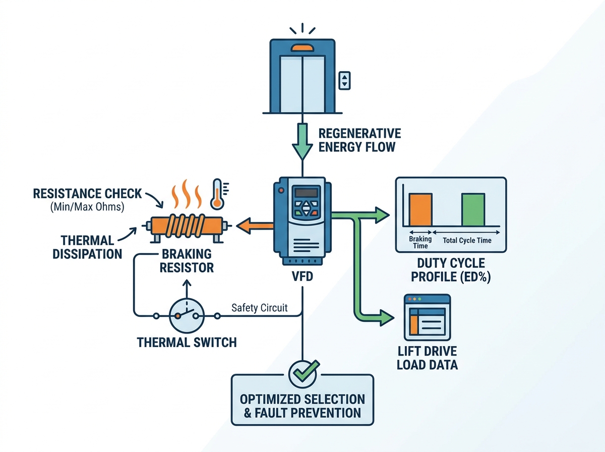
Elevators generate significant regenerative energy during heavy braking. They also produce extreme kinetic energy when moving heavy loads downward. Failing to manage this energy risks immediate system shutdown. It heavily exposes critical control components to severe damage. Selecting the correct braking resistor is never a generic sizing exercise. It requires precise alignment with specific variable frequency drive limits. You must also profile the duty cycle accurately. Furthermore, you must implement stringent thermal management protocols. This comprehensive guide breaks down the critical evaluation criteria for engineers. We cover everything from baseline resistance calculations to advanced physical thermal monitoring. Our actionable insights help engineering and procurement teams confidently shortlist equipment. By following these steps, you will easily specify the right dynamic braking hardware. This ensures safe, continuous mechanical operation across your daily building management tasks.
Key Takeaways
Resistance constraints: Staying within the minimum and maximum ohmic values of the elevator inverter is non-negotiable to prevent IGBT (Insulated-Gate Bipolar Transistor) failure or under-braking.
Duty cycle realities: Accurately calculating the braking time versus cycle time (ED%) dictates the necessary power rating and prevents catastrophic overheating.
Thermal integration: Proper enclosure selection (IP ratings) and thermal switch integration are mandatory for system safety and compliance.
Fault mitigation: Exact component matching serves as the baseline for reliable elevator inverter fault prevention.
The Business Impact of Mismatching an Elevator Inverter and Braking Resistor
An incorrectly sized resistor causes severe operational problems. It leads to frequent variable frequency drive (VFD) overvoltage trips. This strands passengers unexpectedly between floors. It also heavily increases emergency maintenance callouts. Building managers face frustrated tenants and high repair bills. You must match the hardware perfectly to avoid these outcomes. A successfully implemented resistor maintains smooth deceleration every time. It protects the VFD from dangerous regenerative voltage spikes. It also operates well within safe thermal thresholds. You can expect a reliable component lifespan exceeding ten years.
There are serious implementation risks if you ignore proper sizing. Undersizing leads directly to resistor burnout. It creates severe machine room fire risks. Oversizing incurs an unnecessary footprint expansion. It also wastes upfront capital budgets. Advanced regenerative drives certainly exist today. However, traditional dynamic braking resistors remain essential. They are the most cost-effective fail-safe for standard low-to-mid-rise applications. They offer unmatched reliability for everyday use. You just need to ensure your sizing math is completely precise. Always verify compatibility with your specific elevator inverter before installation.
Evaluating Resistance Thresholds with Lift Drive Load Data
The core calculation lens relies on strict parameters. The inverter DC bus voltage establishes the operational rules. The braking chopper limits dictate the absolute minimum allowable resistance. You must gather precise mechanical metrics first. We emphasize pulling accurate lift drive load data before specifying anything. You must test the empty car moving upward. You also need data for the fully loaded car moving downward. Gravity dictates that these scenarios generate peak regenerative energy. You must know these exact peaks to proceed safely.
Let us evaluate the specific ohmic value dimensions. These determine how energy safely leaves the system. If the resistance is too low, disaster strikes quickly. It draws excessive current immediately upon braking. This destroys the internal braking chopper entirely. What if the resistance is too high? It fails to dissipate regenerative energy fast enough. This triggers frustrating DC bus overvoltage faults. Always default to the VFD manufacturer manual. Use their recommended minimum resistance value. This serves as your baseline design constraint.
Resistance Threshold Evaluation Matrix
Ohmic Value Condition
System Behavior
Component Risk Profile
Below Minimum Allowed
Draws excessive electrical current instantly
Destroys IGBTs and internal braking chopper
Optimal Match
Dissipates energy smoothly at safe currents
Safe, long-term operation within normal limits
Above Maximum Allowed
Dissipates energy too slowly
Frequent VFD overvoltage faults and system lockouts
Profiling the Duty Cycle (ED%) and Peak Power Requirements
Elevator applications are highly cyclical by nature. They do not run continuously like conveyor belts. Therefore, continuous power ratings are less relevant here. You must focus on peak braking power instead. You also need to calculate the cyclic duration factor (ED%). The duty cycle calculation is straightforward but critical. You divide the braking time by the total cycle time. This reveals the exact percentage of active braking load.
Consider the typical duty cycle realities for elevators:
Standard residential lifts typically operate between 10% and 20% ED.
High-traffic commercial lifts face constant demands.
These busy lifts require much higher ED% ratings.
They also demand a significantly larger physical thermal mass.
You have different physical solution approaches to choose from. Wire-wound resistors handle continuous loads exceptionally well. They dissipate moderate heat over longer periods stably. Aluminum-housed resistors offer different benefits altogether. They are much better for high-peak, short-duration kinetic energy dissipation. Grid resistors serve heavy-duty industrial applications best. You must align the resistor physical build to your calculated ED%.
Massive thermal capacity; large physical footprint
Conducting Physical Heat Checks and Environmental Selection
Braking resistors convert kinetic energy entirely into heat. They have no other way to release it. Therefore, machine room ambient temperatures matter immensely. A hot room directly impacts the resistor cooling ability. If ambient temperatures exceed 40°C, the resistor struggles. It cannot shed heat effectively into already warm air. This requires you to derate the resistor power capacity manually.
Enclosure selection and IP ratings dictate environmental survival. IP20 or IP21 enclosures feature open slats. They are standard for clean, climate-controlled elevator machine rooms. They allow maximum natural airflow for rapid cooling. IP54 or IP65 enclosures are entirely different. They are necessary for harsh, dusty, or unconditioned hoistway environments. Because they trap air, they require heavy derating for heat.
Clearance and ventilation rules prevent secondary damage. You must maintain strict mandatory physical spacing around the unit. We usually recommend a minimum of 200mm clearance. This applies to all sides of the resistor enclosure. Proper spacing prevents localized overheating of adjacent control panels. It also stops nearby electrical wiring insulation from melting.
Integrating Components for Elevator Inverter Fault Prevention
Safety overlays represent the final engineering defense line. The resistor must never operate in complete isolation. It requires active monitoring to function safely. This continuous oversight guarantees reliable elevator inverter fault prevention. You must mandate the use of integrated thermal switches. These bi-metallic klixons react instantly to excessive casing temperatures.
The control logic wiring requires careful electrical planning. You must wire the thermal switch directly into the safety circuit. Alternatively, wire it to the main power contactor. If the braking chopper fails closed, current flows continuously. The thermal switch must physically sever the main power. This immediately stops the continuous current flow. It definitively prevents localized fires and catastrophic meltdowns.
Verification finalizes the safe installation process. You must perform regular physical and software heat checks. Do this thoroughly during the initial system commissioning. Technicians should use infrared thermal imaging cameras. They must also monitor the VFD diagnostic software simultaneously. This validates all your theoretical engineering calculations against reality. It proves the system sheds heat exactly as designed.
Shortlisting Logic and Procurement Next Steps
Procurement teams need a clear decision matrix for shortlisting. You cannot buy resistors based on price alone. You must follow a strict sequential checklist. This ensures the hardware meets both technical and safety codes. Use the following logic to evaluate vendor proposals carefully.
Spec Match: Does the ohmic value precisely match the VFD manual? Furthermore, does the wattage safely cover the peak load data?
Safety and Compliance: Does the unit include a built-in thermal overload switch? Does it meet local electrical codes like UL, CE, or CSA?
Form Factor: Does the physical footprint fit the intended machine room space? Does the IP rating match the environmental conditions?
You must take one specific actionable next step. Never issue a purchase order blindly. Require vendors to provide comprehensive temperature rise graphs. These graphs must be based on your specific duty cycle. If they cannot provide this data, find another vendor. Empirical thermal data prevents expensive mistakes post-installation.
Conclusion
Proper braking resistor selection bridges a crucial gap. It connects theoretical electrical engineering with safe mechanical operation. It ensures passengers experience smooth rides without unexpected emergency stops. Accurate selection also protects expensive variable frequency drives from premature failure. You must evaluate the resistance limits strictly. You must also understand your environmental heat constraints perfectly.
Never guess power ratings based on motor horsepower alone. That outdated method leads directly to dangerous overheating. Always calculate your needs based on accurate lift load data. Respect the inverter minimum and maximum resistance limits universally. Finally, hardwire physical thermal protections into the safety circuit. Following these steps guarantees long-term reliability for your elevator systems.
FAQ
Q: What happens if I use a braking resistor with lower resistance than the elevator inverter specifies?
A: It will draw current exceeding the braking chopper’s rating, leading to immediate and costly damage to the inverter's internal IGBTs.
Q: How do I determine the actual duty cycle for my elevator application?
A: Measure the worst-case scenario: the duration of braking during a fully loaded descent divided by the total time of a complete round trip, expressed as a percentage.
Q: Why is my current braking resistor overheating despite matching the power rating?
A: Overheating usually indicates an underestimated duty cycle, insufficient physical ventilation in the machine room, or a failing braking chopper that is leaking continuous DC current.