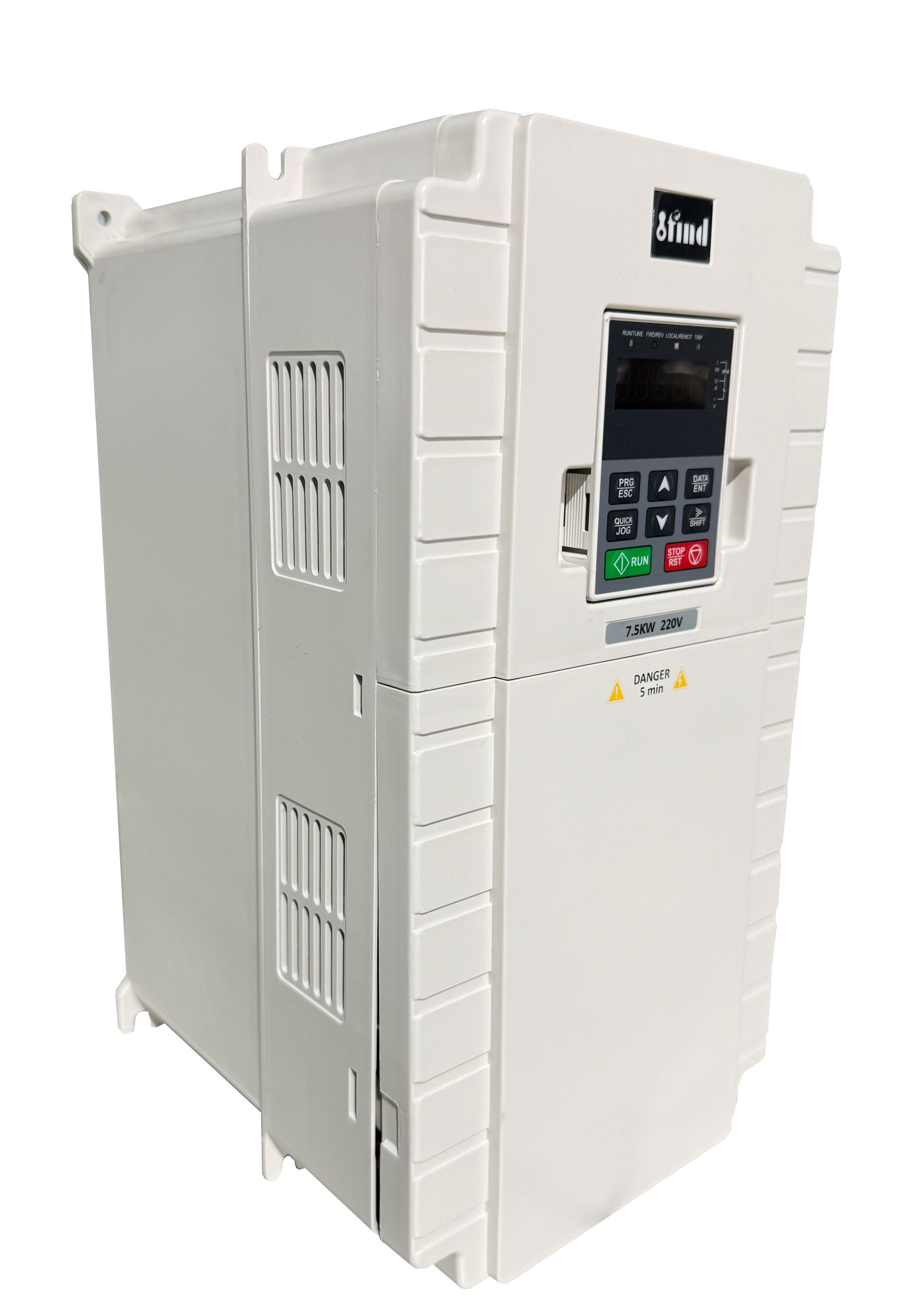
Sizing an elevator motor controller based solely on basic motor nameplate data introduces major operational risks. Relying on static horsepower or kilowatt ratings ignores the complex dynamic forces at play in vertical transportation. When engineers use generic variable frequency drive sizing methodologies, they typically face one of two costly outcomes. The first is under-sizing, which leads to frequent fault trips, rollback incidents, and poor ride quality. The second is over-specifying, which wastes capital on unnecessary electrical capacity and oversized cooling infrastructure.
To avoid these extremes, you must analyze specific, real-world load metrics. Variable weights, aggressive duty cycles, mechanical system imbalances, and emergency power requirements dictate the physical demands placed on the controller. Evaluating these dynamic load profiles allows you to select a purpose-built Lift Drive Inverter that ensures absolute passenger safety, maximizes energy efficiency, and meets strict elevator code compliance.
Key Takeaways
Peak vs. Continuous Demand: Selecting a lift drive inverter requires prioritizing short-term overload capacity (peak current during acceleration) over continuous running current.
Load-Weighing Integration: Advanced drives must seamlessly interface with under-car or rope load-weighing devices to apply precise pre-torque and prevent rollback.
Closed-Loop Necessity: For environments with highly variable loads, a closed loop lift inverter is critical for maintaining zero-speed control and precise floor leveling.
Emergency Power Sizing: Accurate load data is non-negotiable for correctly sizing Uninterruptible Power Supplies (UPS) and battery systems for Automatic Rescue Devices (ARD).
Cost Optimization: Accurately defining the load class early in the specification process prevents expensive overdesign while ensuring the drive matches actual operational realities.
The Role of Load Data in Lift Drive Inverter Selection
Accurate load data serves as the foundational blueprint for any successful elevator installation or modernization project. Good load data goes far beyond a simple maximum weight capacity. It requires high granularity, capturing the exact mechanical imbalances, acceleration profiles, and worst-case scenario modeling. When you gather precise data, you establish clear success criteria for the system. This data dictates how the controller will manage current output, handle thermal dissipation, and react to sudden mechanical shifts.
Field engineers know that walking into a motor room and simply reading the 20HP tag on an old DC machine is a recipe for failure. You have to calculate the suspended mass, the roping ratio, and the friction of the guide rails. Without this granular data, you risk premature equipment failure and compromised passenger safety. The drive must handle the physical reality of the shaft, not just the theoretical numbers on a piece of paper.
Static vs. Dynamic Loads
Understanding the fundamental difference between static and dynamic loads dictates the correct equipment specification. Static load refers to the constant, unchanging weight of the physical elevator components. This includes the empty cab, the sling, the suspension ropes, the traveling cables, and the counterweight. If an elevator simply hung in a shaft without moving, the static load would be the only force acting on the motor and brake.
Dynamic loads introduce entirely different physical forces. When the elevator begins to move, it must overcome static friction (stiction) and the massive inertia of the entire mechanical system. During acceleration, deceleration, and high-speed travel, dynamic forces multiply the effective weight the motor must handle. A cab that weighs 5,000 pounds statically might exert the equivalent of 8,000 pounds of force on the motor during a rapid acceleration phase. Accurate load data models these dynamic peaks, ensuring the controller has the electrical headroom to push the required current without tripping offline.
Consider the roping ratio. A 2:1 roped car moves half as fast but lifts twice the weight compared to a 1:1 roped car. The dynamic inertia changes completely based on this mechanical arrangement. The drive must be sized to handle the specific inertia profile of the roping system, not just the raw weight of the cab.
The Impact of Variable Loads on Elevator Drive VFD Performance
Standard industrial AC drives are built to run fans, pumps, and conveyors. These applications feature predictable, relatively constant loads. Elevators operate in a completely different reality. An elevator drive VFD must handle rapid, unpredictable load shifts. A cab might travel upward completely empty, and then travel downward packed with heavy freight. Generic drives struggle with these violent load shifts because their internal algorithms are tuned for steady-state operation.
When faced with a sudden weight change, a standard drive often overcompensates or undercompensates, resulting in harsh jerks or motor stalling. Purpose-built lift inverters solve this problem by dynamically adjusting frequency and voltage in real-time. They are engineered to handle precise frequency conversions across a massive spectrum, typically from 1 to 800 Hz. When a sudden load shift occurs, the dedicated inverter recalculates the necessary torque vector instantly. It adjusts the magnetic flux in the motor to match the exact physical demand of the variable weight.
Essential Load Metrics for Specifying a Lift Elevator Inverter
Engineers must evaluate several specific dimensions of load data before shortlisting a controller. You cannot simply match the motor's horsepower rating to the drive's horsepower rating. You must break down the data points into features-to-outcomes, linking specific electrical metrics directly to the physical performance of the elevator cab.
Peak Current (Overload Capacity) vs. Continuous Current
The most common sizing error in vertical transportation is selecting a drive based on continuous running current. Elevators spend very little time running at a continuous, steady state. Their operation consists almost entirely of starting, accelerating, decelerating, and stopping. Therefore, the peak current rating is the primary metric for success.
Elevator applications typically require inverters with an overload capacity of 150% to 200% for durations ranging from 10 to 60 seconds. When the brake lifts and the motor begins to turn the sheave, it requires a massive influx of current to overcome inertia. If you specify a standard industrial VFD that only offers a 110% overload capacity for 60 seconds, the drive will fault out on overcurrent during a fully loaded start. A dedicated lift elevator inverter is physically constructed with larger capacitors and more robust power modules specifically to handle these extreme, short-term current spikes without sustaining internal damage.
To calculate the true peak current requirement, you must follow these specific steps during the site survey:
Measure the exact weight of the empty cab and sling assembly.
Calculate the maximum passenger or freight capacity based on the platform square footage.
Determine the counterweight overbalance percentage (typically 40% to 50%).
Factor in the mechanical efficiency of the gearbox (if geared) or the direct-drive sheave (if gearless).
Apply a 1.5x to 2.0x multiplier to the continuous current draw to establish the required peak overload rating.
Duty Cycle and Thermal Dissipation
Load data must include the anticipated duty cycle, which is typically measured in motor starts per hour. High-frequency start/stop cycles place immense thermal stress on the inverter's Insulated-Gate Bipolar Transistors (IGBTs). Every time the drive pushes peak current to accelerate the cab, the IGBT junction temperature spikes. If the elevator stops and starts again before the heat sink can dissipate that thermal energy, the internal temperature compounds.
You must calculate the required cooling or derating based on the expected trips per hour. A drive installed in a low-traffic residential building faces a vastly different thermal reality than the exact same drive installed in a high-traffic commercial hospital. If the load data indicates 180 starts per hour, you may need to oversize the drive simply to gain a larger heat sink, or you must specify additional forced-air cooling in the machine room to prevent thermal tripping.
Counterweight Balance and Regenerative Loads
Elevator systems utilize a counterweight to balance the load, typically set at 40% to 50% of the cab's total capacity. This mechanical balance dictates whether the motor is consuming power (motoring) or generating power (regenerating). If an empty cab travels upward, the heavier counterweight pulls it down. The motor acts as a generator, holding the system back to prevent overspeeding. The same happens when a fully loaded cab travels downward.
This regenerative energy must go somewhere. If the drive cannot dissipate it, the DC bus voltage will spike, causing a catastrophic overvoltage fault. Load data tells you exactly how much regenerative energy the system will produce. Based on this data, you must evaluate the need for dynamic braking resistors, which burn off the excess energy as heat, or a fully regenerative drive system that feeds the clean power back into the building's electrical grid.
Cab Load Condition
Direction of Travel
Motor State
Energy Flow
Empty Cab (Lighter than Counterweight)
Up
Generating
Energy flows from motor to drive (Regen)
Empty Cab (Lighter than Counterweight)
Down
Motoring
Energy flows from drive to motor (Consuming)
Full Cab (Heavier than Counterweight)
Up
Motoring
Energy flows from drive to motor (Consuming)
Full Cab (Heavier than Counterweight)
Down
Generating
Energy flows from motor to drive (Regen)
Emergency Rescue Operations: UPS and Battery Load Requirements
Modern safety codes require elevators to safely evacuate passengers during a total power failure. This requires an Automatic Rescue Device (ARD) powered by a Uninterruptible Power Supply (UPS) or a dedicated battery bank. Accurate maximum load data is non-negotiable for sizing these emergency systems.
The maximum dynamic load dictates the power rating and the specific inverter voltage required for the battery backup. During a power failure, the ARD supplies low-voltage DC directly to the drive's DC bus. The drive must then determine the path of least resistance based on the current load imbalance, carefully releasing the brake and moving the cab to the nearest floor at a reduced speed. If the load data is incorrect, the UPS will be undersized, the batteries will drain instantly under the peak current demand, and the passengers will remain trapped.
Advanced Load-Weighing and Pre-Torque Requirements
To achieve perfect ride quality, the controller must know exactly how much the cab weighs before the mechanical brake releases. This requires seamless communication between physical sensors and the drive's internal processing logic. The way the inverter handles this physical data determines whether the elevator departs smoothly or jerks violently.
Interfacing with Load-Weighing Devices
Elevator systems utilize highly sensitive load cells to measure passenger or freight weight. These sensors are typically installed under the cabin floor, on the crosshead, or directly attached to the suspension ropes. As weight enters the cab, the strain gauges inside the load cells deform slightly. This deformation alters their electrical resistance.
The load-weighing device translates this physical change into an electrical signal and transmits it directly to the drive. Common communication methods include 0-10V analog signals, 4-20mA current loops, or digital CANbus messages. The drive's microprocessor takes this real-time weight data and compares it against the known static weight of the counterweight. It calculates the exact directional imbalance of the system in milliseconds, preparing the motor for the exact amount of work required.
Why a Closed Loop Lift Inverter is Essential
Knowing the weight is only half the battle; applying the correct force requires absolute precision. This is where a closed loop lift inverter becomes essential. A closed-loop system utilizes a rotary encoder mounted directly on the motor shaft. This encoder feeds exact rotor position and speed data back to the drive thousands of times per second.
By combining the load-weighing data with the encoder feedback, the drive executes a function called pre-torque. Before the mechanical brake coils even energize to release the brake, the drive pushes the exact amount of current into the motor required to hold the specific load at zero speed. The outcome is flawless. The brake lifts, and the cab does not move a single millimeter. It eliminates rollback entirely, ensures perfectly smooth departures, and maintains precise floor leveling regardless of whether the cab contains one person or a maximum capacity load.
Evaluating Lift Drive Inverters by Application Type
Not all elevators serve the same purpose, and load data dictates the choice between different tiers of inverter technology. The building's specific use case heavily influences the overall value and the conceptual trade-offs you must make during the specification process.
Passenger Elevators (Ride Quality & Precision)
In passenger applications, particularly in high-rise commercial buildings or luxury residential towers, human comfort is the primary metric. The load data here focuses heavily on jerk rates (the rate of change of acceleration) and smooth S-curve profiles. Passengers are highly sensitive to sudden movements or vibrations.
For these applications, the trade-off strongly favors premium closed-loop systems over standard open-loop VFDs. The load data dictates that the drive must execute flawless pre-torque and maintain micro-millimeter leveling accuracy to prevent trip hazards at the floor landings. The investment in a high-end controller pays off directly in tenant satisfaction and reduced maintenance calls related to ride quality complaints.
Heavy-Duty Cargo, Freight, and Data Center Elevators
Freight elevators operate in a brutal mechanical environment. The load data here focuses on extreme variable weights and impact loading. Consider a data center elevator moving heavy, highly sensitive server racks, or an industrial freight cab where a 5,000-pound forklift drives directly onto the platform to deposit a 4,000-pound pallet.
This scenario creates massive, instantaneous dynamic shocks. The suspension ropes stretch, the sheave deflects, and the load shifts violently. You must specify drives capable of handling specific industrial load classes. The load is rarely evenly distributed. Choosing the right load class early in these specialized environments prevents catastrophic drive failures. The inverter must possess aggressive torque-proving capabilities and massive overload reserves to maintain control of the motor when a forklift suddenly drops thousands of pounds into the cab.
Freight Load Class
Description
Inverter Impact
Class A
General Freight (Hand trucks, manual loading)
Standard overload capacity (150%) is usually sufficient. Gradual load changes.
Class B
Motor Vehicle Loading (Cars, light trucks)
Requires high peak current capacity to handle the sudden rolling weight of a vehicle entering the cab.
Class C1
Industrial Truck Loading (Forklift travels with load)
Industrial Truck Loading (Forklift does not travel)
Massive point-loading on the sill. Drive must hold zero speed perfectly during violent weight transfers.
Implementation Risks: Sizing and Specification Pitfalls
Even with good load data, engineering and procurement teams often make critical errors during the decision stage. Misinterpreting the data or applying generic industrial rules of thumb to elevator applications leads to significant implementation risks.
Overdesigning Load Classes
There is a strong temptation to look at the maximum theoretical load and specify a drive that is vastly oversized just to be safe. This approach carries significant financial risk. Specifying a 100-horsepower drive for a system that will never realistically exceed a 40-horsepower dynamic peak wastes capital on the drive itself, the oversized wiring, the larger breakers, and the heavier contactors.
Right-sizing requires a framework that balances cost control with safety margins. You must analyze the building's actual traffic analysis. If the mechanical system or building traffic will never reach the theoretical maximum, you can safely specify a drive that matches the realistic peak demand while still maintaining the code-required 150% overload safety factor.
Underestimating High-Frequency Start/Stop Cycles
Conversely, ignoring the duty cycle data leads to premature inverter failure. If you size the drive based solely on the peak weight but fail to account for the fact that the elevator will run 200 times an hour, the drive will burn up. The thermal constraints of the IGBTs will be exceeded rapidly.
The mitigation strategy is mandatory thermal modeling. You must review the manufacturer's specific derating curves for ambient temperature and altitude. If the machine room is unconditioned and reaches 105°F (40°C) in the summer, or if the building is located at a high altitude where the air is thinner and less effective at cooling the heat sink, you must derate the drive's capacity. A drive rated for 50 amps at sea level in a cool room might only safely output 40 amps in a hot, high-altitude environment.
Conclusion
Audit your building's traffic patterns to determine the exact motor starts per hour and required duty cycle for the new controller.
Measure the static and dynamic loads of the cab using calibrated load cells before finalizing the drive capacity specification.
Request application-specific derating curves from the inverter manufacturer based on your machine room's maximum summer ambient temperature and geographic altitude.
Verify the communication protocols (analog vs. CANbus) between your chosen load-weighing sensors and the inverter's control board to ensure seamless pre-torque integration.
FAQ
Q: What is the difference between a standard VFD and a dedicated lift drive inverter?
A: A standard VFD is designed for steady-state loads like pumps and fans. A dedicated lift inverter features specialized software for pre-torque capabilities, massive short-term overload capacities (up to 200%), and dynamic frequency adjustments. It is specifically engineered to handle rapid, unpredictable variable loads and complies with strict elevator safety codes regarding brake control and motor contactor monitoring.
Q: How does a closed loop lift inverter prevent elevator rollback?
A: It prevents rollback by combining real-time weight data from load cells with precise rotor position data from a motor encoder. Before the mechanical brake releases, the inverter calculates the exact directional imbalance and pushes the necessary current to hold the motor at absolute zero speed. When the brake lifts, the load is already fully supported by the magnetic field.
Q: Why is overload capacity more important than continuous power rating for an elevator drive VFD?
A: Elevators rarely operate at a continuous, steady state. The highest electrical demand occurs during the initial acceleration phase, where the motor must overcome massive static friction (stiction) and the inertia of the cab, ropes, and counterweight. High overload capacity ensures the drive can deliver this short-term energy spike without tripping.
Q: How do load-weighing devices communicate with a lift elevator inverter?
A: Load cells mounted under the cabin floor or on the suspension ropes measure physical strain as weight is added. They convert this physical deformation into electrical signals. These are transmitted to the inverter via 0-10V analog signals, 4-20mA current loops, or digital CANbus protocols, allowing the drive to perform real-time pre-loading calculations.
Q: Can I use a standard inverter for a heavy-duty cargo elevator?
A: No. Heavy-duty cargo elevators experience extreme variable loads and violent impact shocks, such as a forklift driving into the cab. Standard inverters lack the aggressive torque-proving algorithms and robust regenerative braking management required to handle these massive dynamic shifts, leading to motor stalling, fault trips, and severe safety hazards.
Q: What role does duty cycle play in sizing a lift drive inverter?
A: Duty cycle, measured in trips or starts per hour, dictates the thermal load on the drive's internal components. High-frequency start/stop cycles generate intense heat. If the duty cycle is high, you must specify a drive with a larger physical heat sink or active cooling to prevent thermal overload and premature hardware failure.
Q: How does load data affect the sizing of a UPS or battery backup for an elevator?
A: The maximum dynamic load dictates the exact power rating and inverter voltage required for an Automatic Rescue Device (ARD). During a power outage, the ARD must supply enough low-voltage DC to release the brake and move the heaviest possible load imbalance to the nearest floor. Undersized batteries will fail instantly under peak demand.