Specifying a drive for material handling is vastly different from sizing one for a centrifugal pump or ventilation fan. Under-speccing risks catastrophic drive faults and dropped loads, while over-speccing wastes valuable capital. A purpose-built crane inverter provides the heavy-duty overload capacity and specialized mechanical brake control logic required for safe lifting and lowering. Standard units simply cannot handle the extreme mechanical demands of hoisting applications.
Without these tailored features, you expose your operations to severe safety hazards and operational bottlenecks. This article provides a concrete, engineering-focused framework for gathering the correct motor data, determining braking duty, and outlining precise torque requirements. You will learn exactly what specifications to include so you can submit an accurate Request for Quotation (RFQ). Following this framework ensures your vendor quotes a system fully optimized for your specific lifting requirements.
Key Takeaways
General-purpose drives lack the built-in mechanical brake logic and high overload capacity necessary for safe hoist operation.
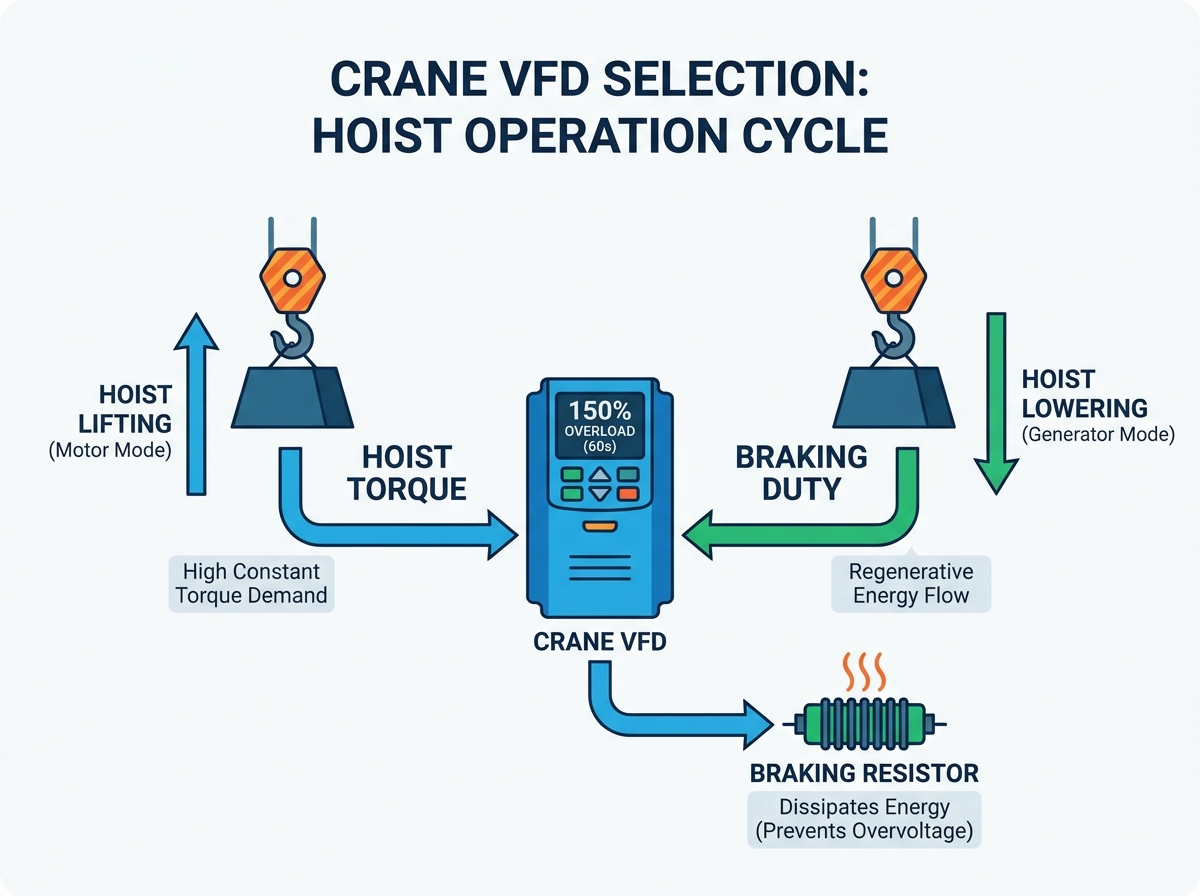
Hoist applications require a dedicated crane inverter sized for at least 150% overload for 60 seconds (Constant Torque).
Deceleration and lowering create regenerative energy; accurately specifying braking duty cycles is critical to prevent DC bus overvoltage faults.
Sizing a three-phase crane VFD must be based on the motor's Full Load Amps (FLA), not just horsepower or kilowatt ratings.
A complete RFQ must include environmental conditions, motor nameplate data, and required safety integrations (like Safe Torque Off).
Why General-Purpose Drives Fail in Material Handling
Selecting the wrong drive architecture often leads to immediate mechanical failures. Many facility managers mistakenly assume any industrial drive can run a hoist motor. This assumption ignores fundamental physics. Standard drives expect quadratic load curves typical of fans and pumps. In those variable torque scenarios, full power is rarely required at low speeds.
Variable vs. Constant Torque
Hoisting operates under severe constant torque demands. A suspended load exerts 100% of its gravitational force regardless of speed. Whether you move a 10-ton steel coil at 5 Hz or 50 Hz, the torque requirement remains absolute. A general-purpose drive typically offers only 110% to 120% overload capacity. This falls completely short during initial lifting phases. Hoists routinely demand 150% overload to overcome static friction and load inertia.
The Risk of Load Slip
Using a standard frequency inverter introduces extreme safety risks. Basic models lack integrated "torque-proving" logic. In material handling, the drive must magnetize the motor and verify sufficient torque generation before commanding the mechanical brake to open. If a basic drive releases the brake prematurely, gravity takes over instantly. The load slips or drops entirely. Specialized firmware prevents this exact scenario by synchronizing motor current feedback and brake relay timing.
Fault Vulnerability
Standard drives also suffer frequent nuisance tripping. When you decelerate rapidly or lower a heavy payload, the motor generates electrical power. This energy flows backward into the drive. Basic units lack the heavy-duty braking choppers required to process this sudden influx. Consequently, they trip on "DC Bus Overvoltage" faults. The drive shuts down, the mechanical brake slams shut, and the sudden stop stresses the entire crane structure.
Sizing for Hoist Torque: Open-Loop vs. Closed-Loop Requirements
Accurate torque sizing guarantees smooth acceleration and reliable holding power. You must define baseline overload specifications immediately in your RFQ. Vendors need to know how aggressively you operate the equipment.
Overload Specifications
Always specify a Heavy Duty (HD) rating for material handling. The baseline requirement is 150% overload for 60 seconds. Many high-performance applications also demand 200% overload for 3 seconds. These buffers allow the motor to punch through initial static friction. They also accommodate momentary load swings without triggering overcurrent protection protocols. Never accept a "Normal Duty" quotation for a lifting application.
Control Methods
Drive control strategies dictate speed precision and safety. You must choose between open-loop and closed-loop configurations based on your specific operational needs.
Open-Loop (Sensorless Vector): This method uses internal algorithms to estimate rotor position. It works exceptionally well for standard traverse movements like bridge and trolley travels. It also handles basic hoists where micro-positioning is unnecessary.
Closed-Loop (Encoder Feedback): This requires a physical encoder mounted on the motor. The encoder sends real-time speed and position data back to the drive. You need this for precision positioning. It is entirely mandatory for holding a load at zero speed (0 Hz hold) without relying on the mechanical brake. Complex multi-hoist synchronizations also require closed-loop control.
Control Method Comparison for Material Handling
Application Requirement
Sensorless Vector (Open-Loop)
Encoder Feedback (Closed-Loop)
Standard Bridge / Trolley
Highly Suitable
Overkill (Unless synchronized)
0Hz Torque Holding (Zero Speed)
Not Possible
Fully Supported
Speed Regulation Accuracy
Moderate (Approx. 0.5%)
Very High (Approx. 0.01%)
Load Drooping Prevention
Adequate for basic loads
Superior holding capability
Application to the RFQ
You must advise vendors clearly in your RFQ regarding control expectations. State your required speed control precision directly. Note whether motor encoders are currently installed on your equipment. If they are, list the encoder type and pulse-per-revolution (PPR) count. This prevents vendors from quoting incompatible control cards.
Braking Duty: Managing Regenerative Energy safely
Braking calculations often represent the most overlooked aspect of crane drive selection. Gravity turns an induction motor into a massive generator during descent.
The Physics of Lowering
When you lower a heavy payload, the load drives the motor faster than the synchronous speed set by the drive. The motor transitions into regeneration mode. It generates electrical energy and sends it backward. This current flows into the drive's internal DC bus. The DC bus capacitors absorb this energy quickly, causing voltage levels to spike. You must dissipate this energy safely to avoid catastrophic drive failures.
Dynamic Braking Options
Facilities generally rely on two primary methods to manage this regenerated power.
Braking Choppers & Resistors: This remains the most common industrial solution. A built-in or external braking chopper monitors the DC bus. When voltage climbs too high, it routes the excess current to a resistor bank. The resistors burn off the energy as heat. To specify this correctly, you must calculate the required wattage and ohmic value based on your duty cycle (e.g., 20% ED vs. 50% ED).
Regenerative Drives (Active Front End): Severe applications require a different approach. If you operate high-frequency duty cycles or perform continuous heavy lowering, resistors become inefficient. An Active Front End (AFE) regenerative drive captures the excess energy and feeds it directly back into your facility's power grid. While initial capital costs run higher, they yield excellent energy savings for high-duty cranes.
RFQ Requirement
Your RFQ must specify the expected maximum braking time and frequency. State the number of operations per hour. Detail the maximum continuous lowering time. Vendors rely on this data to quote the correct resistor bank or determine if an AFE system is necessary. Omit this, and they will likely quote a standard 10% duty cycle resistor, which will overheat and fail under heavy use.
Essential Motor Data for a Three-Phase Crane VFD
Accurate drive sizing relies entirely on comprehensive motor data. Guessing specifications based on mechanical capacity leads to immediate operational faults.
Sizing by Amperage, Not Horsepower
You must select a three-phase crane VFD based strictly on Full Load Amps (FLA). Emphasize this rule during your planning phase. Sizing by horsepower or kilowatts remains a widespread industry mistake. Motors of identical horsepower can draw vastly different amperages. For example, a high-pole, low-speed motor draws significantly more current than a low-pole, high-speed motor of the same horsepower rating. FLA dictates the actual thermal load the drive components must handle.
Required Nameplate Data
Do not accept partial information from your maintenance team. List these non-negotiable data points clearly in your RFQ:
Base voltage: Identify the exact incoming supply (e.g., 460V, 400V, 380V).
Motor frequency: Note whether the motor is designed for 50Hz or 60Hz operation.
Number of poles / Base RPM: This determines the synchronous speed and impacts current draw calculations.
Service factor and insulation class: Verify inverter-duty readiness. Standard motors lack the insulation required to withstand PWM (Pulse Width Modulation) voltage spikes. They degrade quickly without proper Class F or H insulation.
Full Load Amps (FLA): The absolute most critical metric for drive sizing.
Multiple Motors on One Drive
Traverse motions often utilize parallel motors. Dual bridge motors frequently run off a single drive. You must perform specific calculations for these setups. Add the FLA of both motors together. Then, add a 10% to 15% safety margin to the total. Submit this adjusted current requirement in the RFQ. Furthermore, you must install individual motor overload protection devices between the drive and each motor, as the drive can no longer protect a single motor from thermal overload in a parallel configuration.
Control System and Safety Integrations
Modern material handling environments require extensive safety integrations. The drive does not operate in isolation; it functions as the central nervous system for the crane's automated safety protocols.
Mechanical Brake Logic
You cannot compromise on integrated brake control macros. As discussed earlier, the drive must prove current and torque before relaying the brake open command. Furthermore, the drive must seamlessly manage the closing sequence. When a stop command is issued, the drive slows the load to near zero speed. It engages the mechanical brake while holding electrical torque. Only after a predefined delay does the drive cut motor power. This prevents micro-dropping during the stopping phase.
Safety and Compliance
Outline required hardware safety features explicitly. You must demand Safe Torque Off (STO) functionality. Look for compliance with SIL3 (Safety Integrity Level) or PLe (Performance Level e) standards. STO provides a hardware-based override that cuts power to the motor output stage without disconnecting the main drive power. It prevents accidental startups during maintenance or emergency stop conditions. Relying solely on software limits violates modern industrial safety standards.
I/O and Communications
Your RFQ must specify necessary inputs for limit switches. You need dedicated I/O for ultimate up, ultimate down, and directional slowdown limits. Additionally, define your preferred network protocols. If you integrate the crane into a larger plant automation system, note whether you require ProfiNet, Ethernet/IP, or Modbus TCP communication cards for PLC integration.
Formulating Your Drive RFQ (Shortlisting & Next Steps)
Structuring the Request for Quotation properly prevents vendor assumptions. Ambiguous RFQs result in mismatched hardware and extensive change orders later in the project.
The RFQ Checklist
Provide a structured summary of requirements to send to your vendor. A complete package ensures accurate quoting. Include the following sections:
Application type: Specify whether the drive controls a Main Hoist, Auxiliary Hoist, Bridge, or Trolley.
Duty Class rating: Include the CMAA (Class A through F) or FEM duty cycle rating to contextualize operational harshness.
Complete motor nameplate data: Provide the FLA, voltage, RPM, and insulation class as outlined earlier.
Environmental constraints: Define the ambient temperature extremes. Specify required NEMA or IP enclosure ratings (e.g., NEMA 12 for dusty indoor environments, NEMA 4X for corrosive outdoors).
Evaluating Vendor Proposals
When quotes arrive, advise your procurement team to scrutinize them carefully. Vendors often attempt to win bids by undercutting specifications. Look out for omitted braking resistors. Ensure the overload ratings state "Heavy Duty 150%" and not a generic variable torque rating. Finally, check for missing enclosure dimensions. A fully optioned drive with dynamic braking units might not physically fit inside your existing crane electrical panel.
Conclusion
Successful crane VFD selection hinges entirely on precise motor data, realistic torque expectations, and accurate braking duty calculations. Gathering comprehensive nameplate data and understanding the physics of regenerative lowering protects your operational continuity.
Prioritizing these technical specifications over the lowest initial price prevents catastrophic downtime and severe safety hazards. An undersized drive or an improperly configured brake logic controller puts your personnel and facility at immediate risk. Value lies in mechanical reliability and seamless safety integration, not in cutting corners during the procurement phase.
Compile your motor data, record your exact operational duty cycles, and define your control needs using this framework. Having this structured information ready before contacting an integration partner ensures you receive a robust, purpose-built solution designed specifically for your demanding material handling environment.
FAQ
Q: Can I use a standard HVAC or pump VFD for a crane hoist?
A: No. Standard drives are typically rated for variable torque (110%-120% overload) and lack the heavy-duty capacitors, braking choppers, and specific mechanical brake control software required for safe lifting.
Q: Do bridge and trolley drives require the same specifications as a hoist drive?
A: Generally, no. While they still require constant torque ratings, traverse motions do not fight gravity continuously. They typically require less aggressive braking resistors and can often operate safely in open-loop configurations.
Q: What happens if I undersize the braking resistor on my crane inverter?
A: The resistor will overheat and potentially fail, or the drive will fault on "DC Bus Overvoltage" during deceleration, causing the mechanical brake to slam shut and potentially destabilizing the load.
Q: Why do I need to size the drive based on FLA instead of HP/kW?
A: Motors of the same horsepower can draw significantly different amperages depending on their design (e.g., high-pole low-speed motors draw more current). Sizing a three-phase crane VFD by FLA ensures the drive's internal components can handle the actual thermal load.