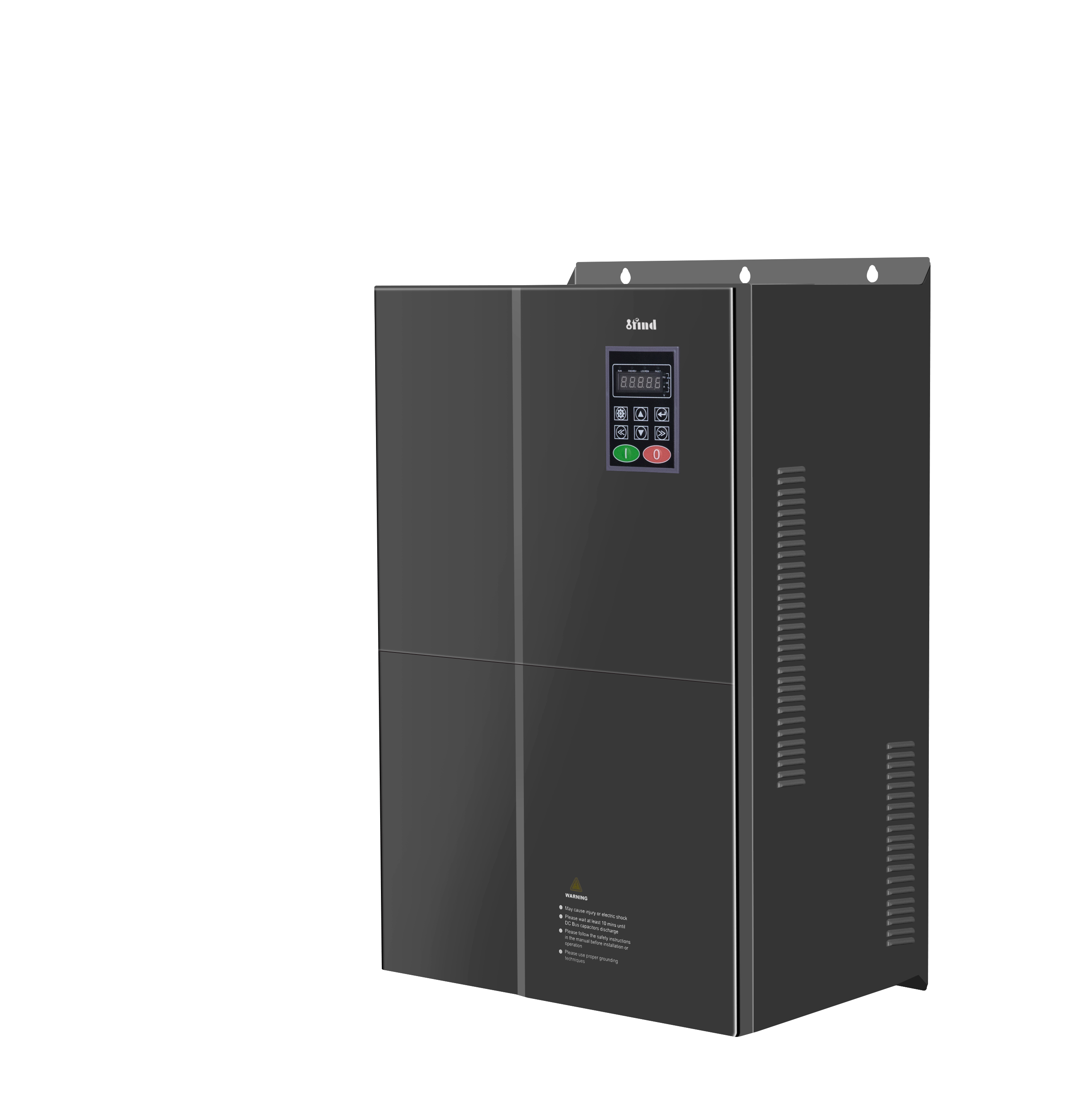
A variable frequency drive, or VFD, is an electronic device used to control the speed and torque of an AC motor. It changes the frequency and voltage supplied to the motor so that the motor can operate according to the actual requirements of the machine.
In many industrial systems, motors do not need to run at full speed continuously. Pumps may need to maintain different flow rates, fans may respond to changing air demand, and conveyors may require controlled acceleration. A VFD allows the motor to match its output to the process instead of operating at one fixed speed.
IFIND provides VFD solutions for pumps, fans, machinery, elevators, textile equipment, printing systems, and other industrial applications.
What Is a VFD?
VFD stands for Variable Frequency Drive. It is also commonly called an AC drive, adjustable frequency drive, variable speed drive, or frequency inverter.
These terms generally refer to equipment that changes the frequency of electrical power supplied to an AC motor. Since motor speed is related to supply frequency, changing the output frequency allows the drive to adjust motor speed.
The synchronous speed of an AC motor can be estimated using this formula:
Synchronous speed = 120 × frequency ÷ number of motor poles
For example, increasing the output frequency generally increases motor speed, while reducing the frequency lowers speed. In an induction motor, the actual speed is slightly lower than synchronous speed because of slip.
A VFD also controls other operating parameters, including:
The appropriate functions depend on the VFD model and the requirements of the application.
How Does a VFD Work?
A typical VFD has four main sections:
AC input rectifier
DC link
Inverter switching stage
Control and feedback system
The VFD first receives AC power from the electrical supply. The input may be single-phase or three-phase, depending on the drive design.
A rectifier converts the incoming AC voltage into DC voltage. In many industrial VFDs, the rectifier uses semiconductor diodes. Some advanced designs use controlled switching devices to improve input performance.
The rectifier stage affects the VFD’s input current, inrush behavior, and harmonic characteristics.
DC Link
The rectified voltage then enters the DC link. This section generally includes capacitors and may also include a DC reactor or choke.
The capacitors smooth the rectified voltage and provide a stable DC bus for the inverter stage. The DC link also separates the input power waveform from the output waveform, allowing the VFD to create a new output with a different voltage and frequency.
Inverter Switching Stage
The inverter stage converts the DC voltage back into AC power. It uses high-speed semiconductor switches, such as IGBTs, to generate a controlled output for the motor.
The voltage at the switching terminals is produced as a series of pulses rather than a perfect sine wave. The motor windings naturally smooth the current, allowing the motor to produce a rotating magnetic field and mechanical torque.
Control and Feedback System
The control system determines how much voltage, frequency, and current the motor needs. The speed command may come from a keypad, analog signal, PLC, PID controller, or industrial communication network.
The VFD continuously monitors operating conditions such as:
Output current
DC bus voltage
Motor speed
Drive temperature
Overload status
Phase loss
Short-circuit conditions
If the drive detects an unsafe condition, it can reduce the output or stop the motor.
What Is PWM in a VFD?
Pulse-width modulation, or PWM, is a common method used to generate the variable-frequency output of a VFD.
The switching devices turn the DC bus on and off at high speed. By changing the width and timing of these voltage pulses, the VFD creates an average output voltage that follows the required waveform.
PWM allows the drive to control motor frequency and voltage with a compact electronic circuit. However, the switching process can also produce electromagnetic interference, motor noise, and additional stress on motor insulation.
The carrier frequency should therefore be selected according to the motor, cable length, operating environment, and application requirements. A higher switching frequency may reduce audible noise, but it can also increase drive losses and electromagnetic interference.
VFD Control Methods
V/F Control
V/F control, also called scalar control or volts-per-hertz control, maintains a suitable relationship between voltage and frequency.
When the output frequency is reduced, the voltage is reduced accordingly. This helps maintain suitable magnetic flux in the motor.
V/F control is relatively simple and is often used for:
It is suitable when the application does not require highly precise speed or torque response.
Sensorless Vector Control
Sensorless vector control estimates motor flux and torque without using a physical encoder.
Compared with basic V/F control, it can provide:
Accurate motor nameplate data is important for sensorless vector control. Some drives also use an auto-tuning process to estimate motor resistance and inductance.
Closed-Loop Vector Control
Closed-loop vector control uses feedback from an encoder or another speed sensor. The VFD compares the commanded speed with the actual motor speed and adjusts the output accordingly.
This method is suitable for applications that require:
Accurate speed regulation
High starting torque
Precise stopping
Stable low-speed operation
Frequent changes in load or direction
Typical examples include elevators, cranes, winding machines, machine tools, and high-performance printing equipment.
For more information about the difference between V/F control and vector control, see the V/F vector inverter guide.
Main Benefits of Using a VFD
Adjustable Motor Speed
A VFD allows the motor to run at the speed required by the process. This can reduce the need for mechanical throttling, bypass systems, gear changes, or other speed-control methods.
Controlled Starting and Stopping
A VFD can gradually increase motor frequency during starting. This reduces starting current and mechanical shock compared with direct-on-line starting.
During stopping, the drive can use a programmed deceleration ramp, DC braking, or a braking resistor, depending on the load and application.
Energy Savings
VFDs can reduce energy consumption when the motor does not need to run at full speed. This is particularly relevant to variable-torque loads such as centrifugal pumps and fans.
However, energy savings are not automatic. The result depends on operating hours, load profile, motor efficiency, drive losses, and the required process output. The U.S. Department of Energy provides additional guidance on adjustable speed drive part-load efficiency.
Reduced Mechanical Stress
Controlled acceleration and deceleration can reduce stress on:
Couplings
Belts
Gearboxes
Shafts
Valves
Pumping systems
In water systems, gradual acceleration can also help limit sudden pressure changes and water hammer.
Motor Protection
A VFD can monitor current, overload, temperature, phase loss, and other conditions. This gives the control system a way to stop the motor or issue a fault signal when operating conditions become unsafe.
Common VFD Applications
Pumps and Water Systems
VFDs are widely used for water supply, irrigation, circulation, wastewater treatment, and process pumping.
The drive can adjust pump speed to maintain a required pressure or flow. Before selecting a VFD, engineers should check the pump curve, total head, motor current, minimum operating speed, and dry-run risk.
Fans and HVAC Systems
Fans often operate under changing airflow requirements. A VFD can adjust fan speed according to temperature, pressure, or ventilation demand.
Common applications include air handling units, exhaust fans, cooling towers, and industrial ventilation equipment.
Conveyors and Material Handling
Conveyors may require controlled starting, adjustable production speed, or synchronization with another machine.
A VFD can help reduce belt shock and maintain smoother material movement. For heavy conveyors, selection should be based on starting torque and overload requirements rather than motor power alone.
Machine tools may require a wide speed range, high low-speed torque, and accurate speed regulation.
Vector control or closed-loop control may be more suitable than basic V/F control when spindle response and cutting performance are important.
Textile and Printing Equipment
Textile and printing machines often require stable speed, smooth acceleration, tension control, and synchronization between different sections.
VFDs can work with PLCs and other drives to coordinate rollers, feeders, winders, and transport mechanisms.
Elevators and Cranes
Elevator and crane applications may require high starting torque, precise stopping, controlled braking, and frequent changes in load direction.
These systems require careful coordination between the VFD, motor, encoder, mechanical brake, safety circuit, and emergency operating system.
How to Select a VFD
VFD selection should consider the complete motor-load system rather than motor power alone.
Motor Data
The following information should be confirmed from the motor nameplate:
Rated power
Rated voltage
Rated current
Rated frequency
Rated speed
Motor phase
Connection method
Insulation class
Cooling method
Rated current is especially important because motors with the same power rating may have different current requirements.
Load Type
Determine whether the load is:
Fans and centrifugal pumps are usually variable-torque loads. Conveyors, mixers, extruders, compressors, and lifting equipment may require constant-torque or heavy-duty operation.
Speed and Torque Requirements
Check the required minimum and maximum speed, starting torque, acceleration time, deceleration time, and overload duration.
A drive that is suitable for normal running may not be suitable for frequent starts, sudden load changes, or high-inertia equipment.
Braking Requirements
High-inertia loads may return energy to the VFD during deceleration. If this energy causes the DC bus voltage to rise, the system may need a braking resistor, braking unit, or regenerative drive.
Operating Environment
Temperature, humidity, dust, corrosive gases, vibration, altitude, and enclosure requirements should all be considered.
The required protection level may be different for a clean electrical cabinet and a dusty machine room.
VFD vs. Soft Starter
A VFD and a soft starter can both reduce starting stress, but they perform different functions.
Feature | VFD | Soft Starter |
Speed control | Provides continuous speed adjustment | Usually operates at fixed speed after starting |
Starting control | Controls frequency, voltage, current, and acceleration | Mainly controls voltage during starting |
Energy-saving potential | Higher for variable-speed loads | Limited after the motor reaches full speed |
Braking | May support DC braking, resistor braking, or regeneration | Usually more limited |
Typical use | Pumps, fans, conveyors, machinery, elevators | Motors that only need smoother starting |
If the process requires continuous speed adjustment, a VFD is normally more suitable. If the motor only needs reduced starting current and then runs at full speed, a soft starter may be sufficient.
Basic Installation and Commissioning
Correct installation and commissioning are essential for reliable VFD operation.
Important points include:
Enter the motor nameplate data accurately.
Use suitable input protection and disconnecting equipment.
Ground the drive, motor, and cable shield correctly.
Keep motor cables separate from control and communication cables.
Check the permitted motor cable length.
Provide sufficient ventilation around the VFD.
Set the minimum and maximum frequency correctly.
Confirm acceleration, deceleration, current limit, and stop settings.
Test motor direction and low-speed operation before full-load commissioning.
If vector control is used, an auto-tuning procedure may be required. The selected auto-tuning method must be suitable for the mechanical condition of the machine.
Frequently Asked Questions
What does VFD stand for?
VFD stands for Variable Frequency Drive. It is an electronic device that controls the frequency and voltage supplied to an AC motor.
Is a VFD the same as a frequency inverter?
In industrial motor control, VFD, frequency inverter, AC drive, and adjustable frequency drive are often used to describe similar equipment.
The important factors are the drive’s voltage, current, control method, motor compatibility, and application rating.
Can a VFD control a single-phase motor?
Most standard VFDs are designed for three-phase induction motors or compatible permanent-magnet motors.
Some specialized models accept single-phase input and provide three-phase output. However, a standard VFD should not be connected to a single-phase capacitor-start motor unless the manufacturer approves the configuration.
Does a VFD always reduce energy consumption?
No. Energy savings depend on the load profile and operating conditions.
The greatest savings are usually available when a pump or fan can operate below full speed for significant periods. If the motor must run at full speed continuously, the energy-saving benefit may be limited.
How do I choose the correct VFD size?
Start with the motor’s rated current, voltage, phase, power, speed, and frequency.
Then evaluate the load type, starting torque, overload requirement, braking energy, operating environment, and required control method. The drive should be selected according to the actual application duty rather than motor power alone.
Can a VFD run a motor above its rated frequency?
It may be possible, but the motor’s mechanical speed limit, cooling, bearings, insulation, load torque, and drive output voltage must be checked first.
Above the base frequency, the motor may operate with reduced available torque. The motor and equipment manufacturer’s limits should always be followed.
What is the difference between VFD and VSD?
VSD means Variable Speed Drive, while VFD means Variable Frequency Drive.
VSD is a broader term that may include different technologies for controlling motor speed. In many industrial applications, a VSD is a VFD, so the terms are often used interchangeably.
Conclusion
A VFD converts fixed-frequency electrical power into adjustable-frequency output for controlling AC motors. Its rectifier, DC link, inverter stage, and control system work together to regulate motor speed, torque, acceleration, braking, and protection.
The correct VFD should be selected according to the motor, load type, speed range, overload requirement, braking needs, and installation environment.
When properly selected and commissioned, a VFD can improve process control, reduce mechanical stress, and lower energy use in suitable variable-speed applications.
Need Help Selecting a VFD?
Share your motor rating, load type, speed range, and operating conditions with the IFIND team. We can help evaluate the suitable VFD control method and configuration for your application.
Discuss Your VFD Application