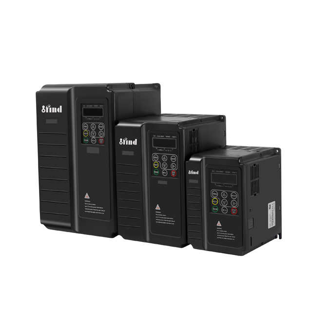
Elevator leveling accuracy goes beyond passenger comfort. It represents a strict safety, accessibility, and liability requirement. ADA compliance demands precise floor alignment to accommodate wheelchairs and mobility devices. Inconsistent leveling creates serious tripping hazards, leading to potential injuries and legal exposure. These operational failures—such as rollback, harsh stops, or overshooting—often stem from misconfigured drive parameters rather than mechanical breakdowns. Field technicians frequently waste hours inspecting brake pads and traction sheaves when the electronic control system actually holds the fault. The Elevator Inverter bridges the gap between the elevator controller's raw commands and the motor's physical output. By translating digital signals into precise voltage and frequency modulation, it dictates the exact stopping profile. We will break down how specific parameter tuning solves these leveling problems, providing actionable steps to optimize your drive configuration for millimeter-level precision.
S-Curve and Deceleration Tuning: Proper configuration of jerk rates and deceleration times is the primary defense against overshooting or undershooting the floor level.
Torque Compensation is Mandatory: Variable passenger loads require precise pre-torque and torque boosting parameters to prevent rollback upon brake release.
Closed-Loop Superiority: Integrating encoder feedback with the elevator inverter's PI (Proportional-Integral) loop is essential for achieving millimeter-level accuracy regardless of environmental variables.
Regenerative and Electrical Stability: Managing DC bus voltage, overvoltage protection thresholds, and frequency bias is critical to prevent drive faults during the final deceleration phase.
Mechanical Synchronization: Inverter parameters must be tuned in tandem with mechanical brake timing; software cannot fully compensate for worn mechanical components.
The Role of the Elevator Inverter in Precision Leveling
You must first define success criteria for elevator leveling before adjusting any software parameters. The industry standard requires accuracy between ±3mm and ±5mm under all load conditions. Tracking the Mean Absolute Error (MAE) helps quantify this performance. You measure MAE across multiple floor approaches using a dial indicator or laser measurement tool in the hoistway. This data reveals exactly how well the inverter controls the motor's final approach. Consistent MAE indicates stable parameter settings and healthy mechanical components. Erratic MAE points directly to load weighing calibration errors, poor PI loop tuning, or fluctuating encoder signals.
Translating signals to motion requires precise electronic control. A lift elevator inverter processes speed reference signals from the main controller. It then modulates voltage and frequency using Pulse Width Modulation (PWM) through its Insulated Gate Bipolar Transistors (IGBTs). This modulation dictates the exact speed and torque of the elevator motor at every millisecond of the flight. The inverter acts as the brain of the hoisting mechanism. It calculates the exact moment to apply electrical braking torque, ensuring the car glides into the floor zone smoothly before the mechanical brake ever drops.
You must evaluate open-loop versus closed-loop systems when diagnosing leveling capabilities. Open-loop systems rely heavily on slip compensation. They estimate motor speed based on output voltage and current draw. Their baseline accuracy is acceptable for low-speed freight lifts or older modernization projects, but they struggle with heavy load variations. Closed-loop systems utilize direct encoder feedback mounted on the motor shaft. They provide real-time tracking accuracy, feeding exact RPM data back to the drive. Closed-loop control is mandatory for high-speed passenger elevators. It guarantees high-precision outcomes regardless of car load, machine room temperature, or rope stretch.
System Type
Feedback Mechanism
Leveling Accuracy
Best Application
Open-Loop Vector
Voltage/Current Estimation (Slip Compensation)
±10mm to ±15mm
Low-speed freight, basic modernizations, short travel distances.
Closed-Loop Vector
Direct Rotary Encoder (Incremental or Absolute)
±1mm to ±3mm
High-speed passenger lifts, high-rise buildings, strict ADA environments.
Core Elevator Inverter Parameters Impacting Leveling Accuracy
Motor Auto-Tuning and Parameter Accuracy
Advanced leveling parameters rely entirely on accurate baseline data. The elevator drive inverter must perform an auto-tune sequence before you attempt to adjust any leveling speeds or PI gains. You can execute a static or rotational auto-tune. Rotational tuning yields the best results because it spins the motor without the ropes attached. It accurately maps motor stator resistance, rotor resistance, mutual inductance, and leakage inductance. It also calculates the exact no-load current and power factor. You cannot skip this step during commissioning. If you manually enter nameplate data without auto-tuning, the drive operates on assumptions rather than physical realities.
Accurate baseline motor data enables high tracking efficiency. The inverter uses this mathematical model to calculate precise magnetic flux. Proper flux control ensures the drive tracks the required speed profile without deviation during the critical deceleration phase. If the motor map is wrong, the inverter will apply incorrect current vectors. This always leads to poor leveling accuracy, motor overheating, and unnecessary acoustic noise in the machine room.
Acceleration, Deceleration, and S-Curve Profiles
Deceleration time dictates your stopping distance. This parameter measures the time required to transition from contract speed to zero speed. It directly affects the distance from the hoistway deceleration switch to the absolute floor level. If you set this time too short, the car stops abruptly, throwing passengers off balance. If you set it too long, the car overshoots the floor and triggers a releveling sequence. You must match this parameter to the physical placement of the hoistway switches and the vane readers.
S-Curve jerk settings round the sharp corners of the linear speed profile. You adjust four distinct jerk rates: initial acceleration, final acceleration, initial deceleration, and final stopping jerk. The final stopping jerk is the most critical for leveling. These parameters prevent abrupt transitions. Harsh stops cause the car to bounce on the suspension ropes. Bouncing ruins leveling precision and causes the encoder to read fluctuating speeds. Smooth S-curves ensure the car settles into the floor zone perfectly without mechanical oscillation.
You face a constant trade-off when tuning these profiles. Aggressive deceleration yields shorter flight times, which improves building traffic efficiency and reduces wait times. However, it degrades passenger comfort and makes leveling precision much harder to control. You must find the balance using a systematic approach:
Set the linear deceleration time to match the physical distance of the slowdown switches.
Increase the final stopping jerk parameter to soften the transition into creep speed.
Run the car empty and measure the stopping distance.
Run the car with full test weights and measure the stopping distance.
Adjust the S-curve rounding until the stopping distance is identical under both load conditions.
Creep Speed, Frequency Limitation, and Stop Frequencies
Creep speed is the final leveling speed. It is the low-frequency parameter used just before the mechanical brake engages. The car travels at this speed through the door zone, usually around 2Hz to 5Hz depending on the gear ratio and sheave diameter. A stable creep speed gives the main controller time to verify the exact floor position via the leveling sensors. It ensures the car is perfectly aligned before cutting power and dropping the brake.
Setting minimum frequency limits is critical for maintaining motor magnetization. Frequency bias ensures the inverter maintains a controllable threshold. It prevents the motor from dropping into an uncontrollable slip state. If the frequency drops too low before the brake drops, you lose electrical control. The car will drift based on the load imbalance between the cab and the counterweight. Proper limits keep the motor magnetized, holding the load steady until the mechanical brake takes over.
Stop frequency thresholds dictate the final resting position. This parameter sets the exact frequency at which the inverter cuts power to the IGBTs. If you cut power at 1Hz, the car might slide a few millimeters depending on brake pad wear. If you cut power at 0.1Hz, the stop is highly accurate but might take too long, causing passenger frustration. You must align this threshold with the brake contactor delay time. The electrical power must remain on just long enough for the brake shoes to clamp the drum or disc.
Implementation risks exist with creep speed adjustments. Setting it too high causes hard, clunky stops because the brake grabs a moving rotor. This wears out the brake linings rapidly. Setting it too low causes the motor to stall. The car stops before reaching the floor zone, requiring the controller to initiate a slow-speed recovery run. You must tune this parameter based on the specific motor's low-speed torque capabilities and the encoder's resolution.
Torque Compensation and Pre-Torque Settings
Load weighing integration is vital for consistent leveling across different passenger capacities. The inverter uses analog signals (typically 0-10V or 4-20mA) from load weighing sensors mounted under the cab floor or on the rope hitches. These sensors measure the exact passenger weight. The inverter adjusts starting and stopping torque based on this weight. An empty car requires different stopping torque than a fully loaded car due to the counterweight imbalance. Analog scaling must be perfectly calibrated in the drive parameters to reflect the actual physical weight.
Pre-torque parameters prevent rollback upon brake release. This function holds the motor at zero speed. It applies full load control while the mechanical brake lifts. The inverter reads the load sensor, calculates the exact holding torque required, and injects that specific current into the stator. This ensures the car does not drop or jump when the brake releases. It provides a seamless transition from mechanical holding to electrical holding, which is critical for a smooth departure and accurate subsequent leveling.
Low-frequency torque boosting overcomes static friction. During the final leveling phase, the motor runs very slowly. Static friction in the gearbox, guide rails, and deflector sheaves increases significantly at low speeds. Torque boosting injects extra current at low frequencies to maintain the magnetic field strength. This pushes the car through the mechanical friction. It prevents the car from stalling just millimeters short of the floor, ensuring the creep speed remains constant regardless of mechanical drag.
PI (Proportional-Integral) Loop Tuning
Proportional Gain (P) determines immediate responsiveness. It controls how aggressively the inverter reacts to speed errors. During the leveling phase, the encoder reports the actual speed back to the drive. If the actual speed drops below the commanded creep speed due to friction or load, the P gain pushes the output frequency back up. High P gain means fast reactions. However, setting the P gain too high causes mechanical vibration, as the drive overcorrects and fights the motor's natural inertia.
Integral Time (I) corrects steady-state errors. It ensures the motor maintains the exact creep speed over time. It compensates for the difference between an empty and full car during the final approach. The I parameter slowly adds or subtracts torque until the speed error is exactly zero. It guarantees the car reaches the exact floor level. A shorter integral time means faster correction, but if it is too short, the system will oscillate.
You need a systematic tuning framework for the PI loop. Always tune the P gain first. Increase P for better responsiveness until you feel a slight vibration in the machine room, then back it off by 10%. Next, adjust the I time to eliminate any lingering speed error. If the car hunts or vibrates at the floor level, your P is too high or your I is too short.
Parameter
Function in Leveling
Symptom of Setting Too High
Symptom of Setting Too Low
Proportional Gain (P)
Reacts to immediate speed errors during final approach.
Motor vibration, harsh acoustic noise, jerky leveling.
Sluggish response, car sags under heavy loads.
Integral Time (I)
Eliminates steady-state error to maintain exact creep speed.
Slow correction, car stalls before reaching the floor.
Speed oscillation, "hunting" for the floor level.
Carrier Frequency and Motor Noise
Carrier frequency impacts signal accuracy and thermal management. This is the switching frequency of the IGBTs inside the drive. Higher frequencies (e.g., 10kHz to 15kHz) reduce audible motor noise. They make the ride quieter for passengers and reduce the annoying high-pitched whine in the machine room. However, high frequencies cause significant inverter heating. They increase switching losses, cause cable heating, and stress the motor's winding insulation due to voltage spikes (dV/dt).
Extremely low carrier frequencies (e.g., 2kHz) degrade the output waveform. A poor, blocky waveform subtly impacts low-speed torque. It reduces leveling precision because the motor receives a less perfect sine wave. The motor may pulse or step at very low speeds, causing a rough final approach. You should keep the carrier frequency between 6kHz and 8kHz for optimal leveling precision and thermal balance. This range provides a smooth enough waveform for accurate creep speed without overheating the drive's heatsink.
Troubleshooting Common Leveling Failures via the Elevator Motor Inverter
Overshooting the Floor Level
Overshooting has specific inverter-related root causes. Deceleration times are often set too long. The car simply runs out of track before reaching zero speed, sliding past the floor level. Creep speed might be set too high, giving the brake too much momentum to stop. Delayed mechanical brake engagement parameters also cause this. If the inverter tells the brake to drop too late, or if the stop frequency is set too low, the car drifts past the floor before the mechanical pads make contact.
Your mitigation strategy requires incremental adjustments. First, verify the physical position of the slowdown switches. If they are correct, reduce the deceleration time in the elevator motor inverter by 0.1-second increments. Test the approach after each change with an empty car and a fully loaded car. Verify the brake drop delay settings. Ensure the brake contactor drops exactly when the stop frequency is reached, leaving no gap between electrical control and mechanical holding.
Undershooting or Stalling Before the Floor
Undershooting happens when the torque limit is reached prematurely. Electronic thermal overload protection might trigger during the final approach if the motor draws too much current for too long. If the S-curve rounding is too aggressive, the car spends too much time at low speed. This drains momentum, causes excessive heat buildup, and eventually causes a stall before the leveling sensors align.
You must adjust torque boost parameters to fix this. Verify your frequency bias settings to ensure the drive isn't cutting power prematurely. Ensure the motor receives adequate current at low frequencies by checking the V/F curve settings or the vector control low-speed torque limits. Check the load weighing calibration. If the inverter thinks the car is empty when it is actually full, it will not apply enough torque to push the heavy car through the final few inches of travel.
Drive Tripping or Jerking from Overvoltage
Elevators generate regenerative power during deceleration. A fully loaded car going down, or an empty car going up, acts as a generator. The motor pushes kinetic energy back into the drive. If the DC bus voltage spikes, it hits the overvoltage protection threshold (typically around 750VDC to 800VDC on a 400VAC system). The drive may abort the deceleration profile to protect its capacitors. It trips, drops the brake immediately, and causes a hard, unsafe stop away from the floor level.
Check the braking resistor parameters immediately. Measure the resistor with a multimeter to ensure it matches the required ohmic value and hasn't burned open. Adjust the overvoltage protection duration settings if necessary. Verify DC bus stability during the final leveling phase using the drive's keypad monitor. Ensure the braking transistor (chopper) is firing correctly. Upgrading the braking resistor wattage or installing a regenerative unit often solves persistent overvoltage trips in high-traffic buildings.
Inconsistent Leveling Under Variable Loads
Inconsistent leveling usually points to load weighing failures or encoder slippage. You may have failed to properly scale the load weighing input during commissioning. Poorly tuned slip compensation parameters in open-loop setups also cause this. The inverter cannot guess the load accurately without proper sensor data. If the car levels perfectly empty but sags when full, the drive is not compensating for the added mass.
Calibrate the analog input parameters on the inverter. Ensure accurate torque scaling from empty to full capacity. Place certified test weights in the car. Check the inverter's monitor parameters to verify it reads 0%, 50%, and 100% load correctly. Adjust the offset and gain parameters until the digital readings match the physical weights. If you are using a closed-loop system, check the encoder coupling. A loose encoder will report incorrect speeds, causing the PI loop to apply the wrong torque.
Implementation Risks and Parameter Tuning Best Practices
You must understand mechanical versus electrical synchronization. Inverter tuning cannot fix worn brake pads. It cannot fix stretching suspension ropes or worn traction sheave grooves. It will not cure faulty, sticking deceleration switches in the hoistway. The inverter parameters must match the physical realities of the equipment. Always inspect the mechanical brake, measure the shoe clearance, and verify the spring tension before altering PI loops or deceleration times. Software cannot outsmart mechanical failure.
Electronic thermal overload and parameter drift pose significant risks. Machine room temperature affects inverter efficiency. Extreme heat degrades sensor accuracy and increases the resistance of the motor windings. Ensure electronic thermal overload protection parameters are set correctly based on the motor's nameplate full-load amps (FLA). They must protect the motor without prematurely tripping during heavy-use leveling sequences. Monitor the drive's heatsink temperature during peak traffic hours to ensure adequate ventilation.
Documentation and baseline backups are non-negotiable in the field. Record all factory default parameters before making changes. Back up the drive configuration to the keypad, a removable SD card, or a PC software tool. Do this before initiating PI loop adjustments. Do it before auto-tuning. Do it before altering S-curves. If your tuning makes the leveling worse, you need a quick, reliable path back to a working state. Never leave a job site without saving the final, working parameter set.
Conclusion
Leveling accuracy is a holistic outcome. It depends heavily on the precise tuning of deceleration, torque, frequency limits, and PI parameters. You must approach these adjustments systematically, verifying mechanical integrity before altering software. Follow these actionable next steps to improve your elevator's performance:
Conduct a baseline ride quality analysis using a digital accelerometer to measure current jerk rates, deceleration profiles, and mechanical vibration during the final approach.
Audit your current inverter parameter sets against the original manufacturer specifications, ensuring the motor nameplate data matches the drive's internal motor map.
Recalibrate your load weighing sensors with physical test weights and adjust the analog input scaling on the inverter to ensure accurate pre-torque upon brake release.
Consult with a certified drive technician to perform a rotational auto-tune and advanced PI loop optimization if the system still struggles with variable loads.
FAQ
Q: What is the ideal creep speed parameter for an elevator inverter?
A: The ideal creep speed typically ranges between 2Hz and 5Hz, depending on the motor and gearbox ratio. It must be fast enough to prevent stalling but slow enough to allow the controller to verify floor position accurately before dropping the brake.
Q: How does load weighing affect elevator leveling accuracy?
A: Load weighing provides analog feedback to the inverter about passenger weight. The inverter uses this data to adjust starting and stopping torque. Accurate load data prevents the car from sagging under heavy loads or overshooting when empty.
Q: Can inverter parameters fix an elevator that overshoots the floor?
A: Yes, adjusting inverter parameters often fixes overshooting. You should first check and incrementally reduce the deceleration time. Next, verify the S-curve jerk settings and ensure the stop frequency threshold aligns with the mechanical brake delay.
Q: What is the difference between open-loop and closed-loop elevator drive inverters?
A: Open-loop inverters estimate motor speed using voltage and current, relying on slip compensation. Closed-loop inverters use an encoder mounted on the motor for real-time speed feedback, providing superior precision and millimeter-level leveling accuracy.
Q: How do I tune the PI loop on an elevator motor inverter?
A: Start by increasing the Proportional Gain (P) until the motor becomes responsive to speed changes without vibrating. Then, adjust the Integral Time (I) to eliminate steady-state errors, ensuring the car maintains the exact creep speed without hunting or oscillating.
Q: Why does my elevator rollback when the brake releases?
A: Rollback occurs when the inverter does not apply sufficient holding torque before the mechanical brake lifts. You must adjust the pre-torque parameters and verify that the load weighing sensor is sending accurate weight data to the drive.
Q: How do overvoltage protection thresholds impact elevator deceleration?
A: During deceleration, the motor generates regenerative power, raising the DC bus voltage. If the voltage hits the protection threshold, the drive may trip to protect itself, causing a harsh stop. Proper braking resistor sizing and parameter configuration prevent this.