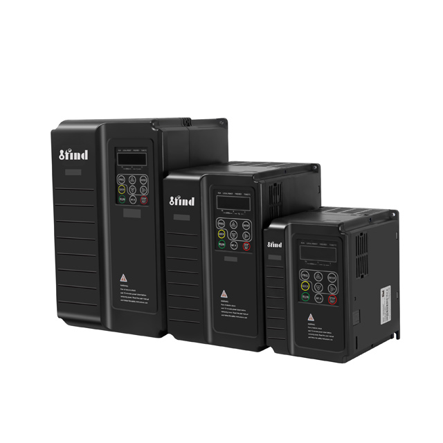
Elevator modernization projects face a strict engineering challenge. You must achieve precise torque control and smooth ride quality without the mechanical complexity of physical rotary encoders. Encoders add failure points, require specialized cables, and complicate installation on older machines. Basic Volts/Hertz (V/Hz) drives fail to deliver the necessary low-speed torque. They cannot prevent rollback or ensure accurate floor leveling under heavy loads. This leaves engineers searching for a reliable middle ground.
Sensorless vector control provides that exact solution. It uses advanced mathematical motor modeling to calculate rotor flux and estimate slip. This delivers near-closed-loop torque response specifically tailored for elevator applications. You get strict rollback prevention and smooth acceleration profiles without mounting external hardware to the motor shaft. By calculating the exact magnetic state of the motor in real-time, these drives bridge the gap between basic open-loop setups and complex closed-loop systems.
Key Takeaways
Mathematical Precision Over Hardware: Sensorless vector control relies on advanced motor modeling and current/voltage feedback to estimate slip and flux, eliminating the need for physical speed sensors.
Independent Vector Control: By controlling the stator current vector relative to the rotor flux vector, these drives decouple magnetizing current from torque-producing current, achieving the high starting torque critical for elevator applications.
Implementation Dependency: Successful deployment requires rigorous static and dynamic auto-tuning to match the inverter's algorithm to the specific motor's characteristics.
Application Boundaries: While highly effective for low-to-medium speed lifts, it cannot hold absolute zero speed indefinitely without mechanical braking or manage speed/torque with the absolute micro-precision of true closed-loop flux vector systems.
The Mechanics of Torque Control in a Sensorless Vector Elevator Inverter
Standard V/Hz drives apply a fixed voltage-to-frequency ratio to the motor terminals. They operate blindly and cannot react dynamically to sudden load changes. When passengers step into a cab, the load shifts instantly. V/Hz drives experience severe torque lag because they do not monitor the actual rotor speed or magnetic flux. This causes poor ride quality, jerky starts, and often triggers overcurrent safety faults. Elevators require maximum torque at zero speed to lift the mechanical brake safely. V/Hz control simply cannot provide this starting power.
Decoupling Flux and Torque Vectors
The microprocessor inside a Sensorless Vector Elevator Inverter solves this torque deficit through advanced mathematics. It separates the stator current into two orthogonal components. One component controls the magnetic flux. The other controls the torque production. Because the stator current vector is controlled relative to the rotor flux vector, the drive adjusts flux magnitude and motor torque independently. This decoupling allows the drive to command instantaneous torque changes. You gain maximum torque availability at extremely low speeds. This ensures the cab remains perfectly still as the brake lifts.
The sequence of events during a typical start command illustrates this control:
The elevator controller sends a run signal and a direction command to the drive.
The drive injects DC current into the motor windings to build the magnetic flux field before releasing the brake.
The drive calculates the required torque based on load-weighing feedback and applies the torque-producing current vector.
The drive sends a signal to open the mechanical brake contactor.
The motor holds the load at zero speed for a fraction of a second while the brake shoes physically clear the drum or disc.
The drive initiates the acceleration S-curve, smoothly ramping up the frequency.
Mathematical Motor Modeling and Slip Estimation
Without a physical encoder, the drive must continuously calculate the rotor's position and speed. It does this using back-electromotive force (back-EMF), voltage, and precise current measurements. The internal algorithm builds a highly accurate mathematical model of the motor. It compares the expected current draw against the actual current draw. The difference between the synchronous speed of the magnetic field and the actual rotor speed is the slip.
The drive calculates this slip in real-time and injects additional frequency to compensate for it. This keeps the elevator speed constant regardless of the load. If a fully loaded cab is moving upward, the motor requires more slip compensation than an empty cab moving upward. The vector algorithm handles this dynamically, adjusting the output frequency hundreds of times per second.
The "Sensorless" Reality
The term "sensorless" can mislead some technicians. While the system is physically open-loop because it lacks a rotary encoder, it operates as a highly responsive closed-loop system mathematically. It relies entirely on the accuracy of its internal motor model. The drive constantly feeds current and voltage data back into its digital signal processor (DSP). This creates a virtual feedback loop. The system reacts to load changes in milliseconds, providing a ride quality that closely mimics a hardware-based closed-loop system.
Evaluating Control Methods: Where the Sensorless Vector Elevator Drive Fits
Selecting the right variable frequency drive (VFD) architecture dictates the success of a lift installation. Engineers typically choose between three primary control methods. Understanding the baseline expectations for each helps you specify the correct equipment for your building requirements.
Solution Categories and Approaches
We categorize lift control into three distinct tiers. Basic V/Hz control sits at the bottom. Sensorless vector control occupies the middle tier. Closed-loop flux vector control represents the top tier. Each method offers different levels of speed regulation, torque response, and installation complexity.
Control Method
Speed Regulation
Starting Torque
Hardware Complexity
Ideal Application
V/Hz Control
2% - 3%
Low (~100% at 3Hz)
Very Low (No encoder)
Basic material hoists, non-passenger applications
Sensorless Vector
~0.1%
High (>150% at 0.5Hz)
Low (No encoder, requires tuning)
Low-to-mid rise passenger lifts, geared traction
Closed-Loop Vector
~0.01%
Maximum (200% at 0Hz)
High (Encoder, wiring, splitter cards)
High-speed, high-rise, gearless traction
V/Hz Control vs. Sensorless Vector
The performance leap from V/Hz to sensorless vector is massive. V/Hz is insufficient for modern passenger elevators due to poor low-speed torque and a complete lack of slip compensation. If you use V/Hz, a fully loaded cab will sag when the brake lifts. A sensorless vector elevator drive eliminates this sag. It acts as the definitive baseline for non-encoder passenger lifts. It provides the necessary torque at fractional frequencies to ensure smooth departures and accurate floor leveling.
Closed-Loop Flux Vector vs. Open Loop Lift Inverter
You must analyze the trade-offs in accuracy and application suitability. Closed-loop systems offer absolute zero-speed torque holding and micro-positioning. They are mandatory for high-speed, gearless high-rise lifts. However, an open loop lift inverter offers 80-90% of this performance with significantly lower installation complexity. You eliminate the cost of the encoder, the fragile feedback cables, and the interface boards. This makes sensorless vector technology ideal for geared traction machines and low-speed modernization projects where mounting an encoder is physically impractical.
Critical Success Criteria for Elevator Applications
Evaluating an inverter requires looking past raw specifications. You must map specific inverter capabilities directly to the passenger experience, operational safety metrics, and long-term equipment reliability. The drive must translate complex vector mathematics into a smooth, unnoticeable ride.
Starting Torque and Rollback Prevention
Rollback occurs when the elevator cab drops slightly before the motor generates enough torque to hold the load. This creates a terrifying experience for passengers. Sensorless vector drives prevent this by pre-torquing the motor. The inverter injects a precise amount of DC current into the stator before the mechanical brake fully lifts. It often utilizes inputs from load-weighing sensors under the cab. The drive calculates the exact torque required to hold that specific weight. When the brake contactor opens, the motor is already holding the load perfectly still.
Field technicians adjust specific parameters to optimize this sequence:
Brake Release Delay: The time the drive waits after injecting DC current before commanding the brake to open.
Zero Speed Hold Time: The duration the drive holds the motor at zero speed while the brake shoes physically retract.
Starting Frequency: The initial frequency applied to overcome static friction in the gearbox and sheaves.
Ride Comfort: Jerk and Acceleration Rates
Human comfort in an elevator depends on controlling the rate of change of acceleration, known as jerk. A sudden spike in torque causes shuddering. The inverter manages this through advanced S-curve profiling. Elevator controllers define four distinct jerk rates during a flight profile. J1 controls the transition from zero speed to constant acceleration. J2 smooths the transition from acceleration to top speed. J3 manages the shift from top speed to deceleration. J4 cushions the final approach to zero speed.
The inverter must process these four distinct jerk commands seamlessly. The drive's microprocessor smooths the transitions between these phases. Combined with rapid torque response, the S-curve ensures the motor perfectly tracks the speed command from the elevator controller. Passengers feel a seamless glide rather than a mechanical pull. If the drive's internal processing is too slow, the motor will overshoot the target frequency, causing the cab to bounce on the ropes.
Energy Efficiency and Flux Optimization
Elevators experience highly variable loads. An empty cab moving down requires very little motor effort because the counterweight does the heavy lifting. The drive's ability to estimate flux and slip enables dynamic flux optimization. During these light-load conditions, the drive automatically reduces the magnetizing current sent to the motor. This intelligent power management significantly lowers thermal stress on the motor windings. It also yields measurable energy savings over the lifespan of the elevator system.
Implementation Realities and Adoption Risks
Deploying sensorless vector technology is not a plug-and-play operation. You must address specific technical hurdles during installation. Ignoring these realities leads to system failures, erratic torque delivery, poor leveling, or frequent drive faults.
The Necessity of Precise Motor Auto-Tuning
The sensorless vector algorithm is entirely useless without accurate motor data. You cannot simply enter the nameplate horsepower and expect it to work. The drive requires rigorous auto-tuning during commissioning to match its internal algorithm to the specific motor being controlled. The drive must measure the stator resistance, rotor resistance, mutual inductance, and leakage inductance.
Static Tuning: The drive injects DC current into the motor without rotating the shaft. This measures basic resistance values. It is useful when the ropes cannot be removed from the traction sheave.
Dynamic Tuning: The drive rotates the motor uncoupled from the load. This accurately measures inductance and calculates the exact slip profile. When performing a dynamic auto-tune, you must physically lift the ropes off the traction sheave. The motor must spin freely without any load. The drive will run the motor up to its base speed, measuring the exact point where the magnetic field saturates. This establishes the no-load current, which is the baseline for all flux calculations.
Thermal Compensation: Good drives adjust their internal motor model as the motor heats up, compensating for changes in copper resistance during heavy usage.
Wiring and Electromagnetic Interference (EMI)
Proper grounding and cable shielding are non-negotiable. Sensorless vector drives generate high-frequency pulse width modulation (PWM) signals. These signals create electromagnetic interference. If you do not use shielded motor cables and ground them properly at both the motor and the drive chassis, this EMI will corrupt the low-voltage signals in the elevator controller. It can also cause false readings in the drive's own current sensors, destroying the accuracy of the mathematical motor model.
Single Motor Limitations
You must understand the electrical reality of vector control. Because a sensorless vector drive actively monitors and controls current based on one specific motor's internal characteristics, it can only control one motor at a time. The mathematical model collapses if you connect multiple motors to a single drive. The drive cannot distinguish between the back-EMF of motor A and motor B. You cannot use this technology in parallel multi-motor configurations. Each motor requires its own dedicated vector drive.
Single Phase Elevator Inverter Considerations
Many residential or light-commercial lifts operate in buildings constrained by single-phase power. Using a single phase elevator inverter with sensorless vector control requires careful engineering. Single-phase input creates significant DC bus voltage ripple. The drive must have oversized DC bus capacitors to smooth this ripple and maintain torque stability. You must also account for harmonic distortion fed back into the residential grid. Engineers often have to derate a three-phase drive by 50% to handle single-phase input safely, ensuring the internal diodes do not overheat during heavy acceleration.
Sourcing and Specifying an Open Loop Lift Inverter
Procurement teams and modernization engineers must evaluate several critical dimensions when shortlisting manufacturers. Pairing the right drive with the right motor ensures long-term reliability and prevents costly callbacks.
Processing Power and DSP Capabilities
The core of any vector drive is its digital signal processor. The drive must handle complex Clarke and Park mathematical transformations in real-time. High-speed microprocessors are an absolute necessity. The execution loop must operate in the sub-millisecond range to prevent torque lag. If the processor is too slow, the motor model falls out of sync with the physical rotor. This results in vibration, acoustic noise, and poor leveling accuracy. Always verify the processor speed and the drive's current loop bandwidth when reviewing technical specifications.
Inverter-Duty vs. Vector-Duty Motor Compatibility
Engineers frequently ask if a standard inverter-duty motor is sufficient for sensorless vector control. The drive can technically control standard inverter-duty motors. However, elevator applications are highly demanding. The drive will run the motor at high torque and very low speeds during leveling and inspection modes. Standard shaft-driven fans fail to provide adequate cooling at 2 Hz or 3 Hz. Therefore, elevator applications often require dedicated vector-duty motors equipped with independent, constant-speed cooling blowers. This prevents the motor insulation from degrading due to excessive heat buildup during low-speed operation.
Motor Type
Cooling Method
Low-Speed Performance
Suitability for Elevators
Standard AC Induction
Shaft-driven fan
Overheats below 15 Hz
Not Recommended
Inverter-Duty
Shaft-driven fan
Tolerates short low-speed runs
Acceptable for light duty
Vector-Duty
Independent blower
Continuous full torque at 0 Hz
Highly Recommended
Conclusion
Sensorless vector control stands as the optimal choice for modernization projects and low-to-mid-rise elevators. It delivers exceptional ride quality and strict torque control where encoder installation is cost-prohibitive or physically impractical. Success depends entirely on the drive's processing power and the accuracy of the motor auto-tuning process. When properly commissioned, these drives eliminate rollback, smooth out acceleration profiles, and reduce long-term maintenance costs.
Base your drive selection on the required starting torque, aiming for at least 150% at 0.5 Hz. Evaluate the quality of the manufacturer's auto-tuning software. Ensure the drive features native integration with elevator controllers, including dedicated brake control logic and load-weighing compensation inputs.
Take the following steps to ensure a successful installation:
Conduct a comprehensive motor audit to verify insulation class, cooling methods, and nameplate data availability before ordering equipment.
Perform a dynamic auto-tune with the motor unroped during commissioning to capture the most accurate inductance and slip measurements.
Verify the drive's firmware includes dedicated elevator S-curve profiling rather than generic industrial pump or fan logic.
Consult with drive application engineers to confirm DC bus sizing if operating on single-phase residential power.
FAQ
Q: What is a sensorless vector elevator inverter?
A: It is a variable frequency drive that uses advanced mathematical models to estimate motor speed and magnetic flux without a physical rotary encoder. It provides near-closed-loop torque control, ensuring smooth acceleration and precise floor leveling for passenger elevators.
Q: How does an open loop lift inverter prevent elevator rollback?
A: The inverter injects DC current to pre-torque the motor before the mechanical brake lifts. By calculating the exact load weight and applying the corresponding torque instantly, it holds the cab perfectly still during the brake transition.
Q: Can a sensorless vector drive hold a motor at absolute zero speed?
A: No. While it provides excellent low-speed torque, it cannot hold a suspended load at absolute zero speed indefinitely without relying on the mechanical brake. Only a true closed-loop system with an encoder can achieve indefinite zero-speed holding.
Q: Why is motor auto-tuning critical for sensorless vector control?
A: The drive relies entirely on an internal mathematical model of the motor. Auto-tuning measures the exact stator resistance, rotor resistance, and inductance. Without these precise values, the drive cannot calculate slip or control torque accurately.
Q: Can I use a single phase elevator inverter with sensorless vector control?
A: Yes, but it requires careful engineering. The drive must have robust DC bus capacitors to handle voltage ripple. You typically need to derate a three-phase drive to manage the increased current load on the input diodes safely.
Q: Do I need a dedicated vector motor, or is an inverter-duty motor sufficient for sensorless vector control?
A: While inverter-duty motors work, elevator applications require high torque at very low speeds. Standard shaft fans cannot cool the motor at these speeds. Therefore, vector-duty motors with independent cooling blowers are highly recommended to prevent overheating.
Q: Why can a sensorless vector drive only control one motor at a time?
A: The drive's algorithm relies on reading the specific back-EMF and current feedback from a single motor to calculate rotor position. Connecting multiple motors scrambles this feedback, causing the mathematical model to fail completely.