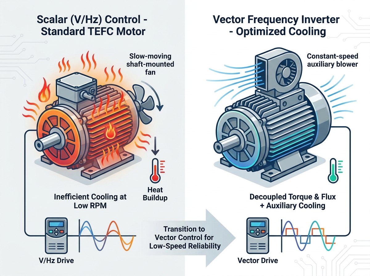
Running standard AC motors at low RPMs via a Variable Frequency Drive (VFD) often creates a sudden, silent threat to your production line. Operators frequently face the immediate risk of unexpected downtime, premature insulation failure, and frustrating thermal tripping. When a motor overheats at low speeds, maintenance teams instinctively suspect a mechanical failure first.
However, experience shows the root cause typically lies elsewhere. Excessive heat usually stems from a hidden mismatch between the operational load profile, specific VFD parameter settings, or the drive's underlying control topology. You cannot solve a programming issue by simply swapping out iron.
You need a clear diagnostic framework to isolate the exact cause of low-speed overheating. This guide will walk you through the transition from software troubleshooting to hardware evaluation. You will discover exactly what to check first, ensuring you choose the right parameter adjustments or hardware upgrades to eliminate thermal issues permanently.
Key Takeaways
Standard Totally Enclosed Fan Cooled (TEFC) motors lose vital cooling capacity below 30 Hz, necessitating diagnostic parameter checks before hardware replacement.
Improper voltage boost settings and high carrier frequencies are the leading programming causes of excess motor heat.
Accurate motor and inverter sizing based on continuous torque requirements—not just horsepower—is critical for low-speed reliability.
Upgrading from a scalar (V/Hz) drive to a vector frequency inverter often resolves low-speed thermal issues by maintaining torque efficiency without over-magnetizing the motor.
The Physics of Low-Speed Thermal Failure in AC Motor Drive Operation
Understanding why motors overheat requires looking at fundamental thermodynamics. We must explain the direct correlation between reduced RPM and decreased cooling efficiency. Most industrial facilities use standard TEFC (Totally Enclosed Fan Cooled) motors. These rely on a shaft-driven fan to push ambient air over the external cooling fins.
When you reduce the operating frequency via a VFD, the motor shaft spins slower. Fan efficiency does not drop linearly; it drops exponentially. At half speed, the cooling airflow drops dramatically, leaving the motor unable to shed the heat it generates. This physical limitation becomes a massive business problem when operators expect continuous production at 15 or 20 Hz.
Furthermore, we must address the heat generation factor itself. Standard AC motor drive operation inherently introduces harmonic distortion. VFDs use Pulse Width Modulation (PWM) to simulate an alternating current. Instead of smooth sine waves, the drive sends rapid, chopped pulses of DC voltage to the stator. This switching action creates harmonic currents. Harmonics do no useful mechanical work. Instead, they manifest entirely as additional thermal stress.
Before you begin troubleshooting, you must define clear success criteria. Your ultimate goal involves achieving the required low-speed torque while maintaining safe motor surface temperatures. You must keep internal temperatures strictly within the manufacturer's insulation class limits.
Class F Insulation: Designed to handle a maximum temperature of 155°C.
Class H Insulation: Designed to handle a maximum temperature of 180°C.
Safety Margin: Always aim to run at least 10°C below the maximum rating to double the insulation lifespan.
Diagnostic Phase 1: Audit Motor and Inverter Sizing
Your first diagnostic step focuses on evaluating load versus capacity. We must frame this evaluation carefully around specific load types. Industrial applications generally fall into two categories: constant torque and variable torque. Your troubleshooting approach changes entirely depending on which load type you drive.
Table: Load Profile Sizing Characteristics
Load Type
Equipment Examples
Low-Speed Torque Demand
Overheating Risk at Low RPM
Constant Torque
Conveyors, Extruders, Hoists
Remains at 100% regardless of speed
Extremely High (Requires maximum current while cooling is minimal)
Variable Torque
Centrifugal Pumps, HVAC Fans
Drops by the square of the speed reduction
Low (Current demand decreases significantly as speed drops)
Running a constant torque application at low speeds draws near-maximum current. The load requires immense twisting force to keep moving. High current pushing through the stator windings generates intense resistive heat (often called I²R losses). Because the shaft fan spins slowly, this heat remains trapped inside the casing.
Many engineers face harsh sizing realities during this phase. Discussing the risks of sizing drives based purely on nameplate horsepower (HP) is critical. Horsepower tells you very little about low-speed thermal capacity. You must focus on Full Load Amps (FLA) and the low-speed torque profiles.
To audit your system effectively, follow this numbered sequence:
Measure the actual running current at your target low speed.
Compare this measurement against the motor's nameplate FLA.
Check the VFD's continuous output current rating.
Verify the duty cycle. Continuous operation demands much stricter sizing than intermittent jogging.
If you find a discrepancy, your capacity planning failed. You must ensure accurate motor and inverter sizing aligns perfectly with the specific continuous low-speed duty cycle your process demands. Undersizing the inverter leads to current clipping and nuisance faults. Undersizing the motor guarantees roasted windings.
Before assuming a complete hardware failure, you must rule out software misconfigurations. Implementation risks often center around poorly adjusted parameters. Incorrect programming frequently mimics hardware thermal overload. Fixing a parameter takes five minutes; replacing a burnt motor takes hours.
V/Hz Ratio and Voltage Boost
In standard scalar drives, the V/Hz ratio maintains a linear relationship between output voltage and frequency. However, at very low frequencies (below 10 Hz), the resistance of the stator windings consumes a disproportionate amount of the supplied voltage. To compensate, technicians often increase the low-frequency voltage boost, also known as IR compensation.
While an aggressive voltage boost helps break away sticky, high-friction loads, it introduces severe risks. Too much boost pushes excessive voltage into the stator at low speeds. This over-magnetizes the motor core. Magnetic saturation generates massive core heat rapidly. A common mistake is leaving the voltage boost cranked up after a temporary mechanical bind clears. Always tune this parameter to the absolute minimum value required to turn the shaft.
Carrier Frequency (Switching Frequency)
The carrier frequency dictates how fast the VFD's internal transistors turn on and off. You will often see this setting adjusted between 2kHz and 15kHz. There is a distinct trade-off to consider here.
Operators frequently raise the carrier frequency to 8kHz or higher to eliminate the high-pitched audible whine coming from the motor. While this makes the factory floor quieter, it dramatically increases heat at the motor terminals. High switching speeds cause rapid capacitive leakage. They also generate severe voltage spikes known as reflected waves. These spikes hammer the first few turns of the motor winding, degrading insulation and generating localized heat. By lowering the carrier frequency back to 2kHz or 4kHz, you can instantly reduce harmonic-induced thermal stress.
Slip Compensation Errors
Induction motors require "slip" to produce torque. Slip is the difference between the synchronous speed of the magnetic field and the actual speed of the rotor. Under heavy loads, the rotor slows down, increasing slip.
Modern VFDs feature slip compensation parameters. The drive attempts to keep the output RPM constant as the mechanical load varies. Note how improperly tuned slip compensation causes chaos. If you enter incorrect nameplate data, the drive miscalculates the required slip. It forces the drive to output unnecessary, excessive current to chase an impossible RPM target. This phantom current drives up the overall thermal load drastically. Best practice dictates verifying that your motor's base RPM and pole count match the drive's software exactly.
Solution Evaluation: When to Transition to a Vector Frequency Inverter
If your parameters are perfectly optimized and your sizing is correct, the thermal issue likely stems from the drive's control topology. We must compare standard Scalar Control (V/Hz) with advanced Vector Control.
Scalar drives struggle significantly at low speeds. They supply a fixed ratio of voltage and frequency, operating effectively blind to the motor's actual rotor position. Because they cannot accurately separate the magnetizing current (flux) from the torque-producing current (load), they default to pushing bulk power. At low frequencies, this blunt-force approach often results in either motor stalling or rapid overheating.
This is where the vector advantage becomes obvious. A vector frequency inverter mathematically decouples these two currents in real-time. By utilizing a highly complex internal motor model, the drive acts like a DC controller for an AC motor.
It calculates exactly how much current must go toward maintaining the magnetic field and how much must go toward turning the shaft. It delivers up to 100% of rated torque at nearly 0 RPM. Because it only supplies the precise amount of current required by the load, you achieve maximum electrical efficiency and minimal waste heat.
You need specific shortlisting logic to justify this upgrade. You should abandon standard V/f drives and invest in vector technology when your operation involves:
Precision low-speed material handling requiring smooth acceleration.
Hoists and cranes that must hold heavy loads at zero speed.
Extruders running highly viscous materials at low RPMs continuously.
Applications where frequent stalling causes unacceptable scrap rates.
Hardware Upgrades: Inverter-Duty Motors and Auxiliary Cooling
When parameter adjustments are fully optimized and your drive topology is adequate, you must address mechanical limitations directly. Sometimes, the physical hardware simply cannot survive the operational environment. You must take concrete next-step actions to ensure scalability.
Inverter-Duty Motor Upgrades
Standard general-purpose motors are not designed to withstand the harsh electrical environment of continuous VFD operation at low speeds. Discussing NEMA MG1 Part 31 compliance is critical here. If you upgrade, you must look for this specific standard on the motor nameplate.
Inverter-duty motors utilize superior winding insulation systems. They feature higher quality magnet wire and advanced varnishes designed to handle repetitive peak voltage spikes up to 1,600V. Furthermore, they resist thermal degradation far better than older standard motors. An inverter-duty motor operates safely across a much wider speed range, often providing a 1000:1 constant torque turndown ratio when paired with a high-performance vector drive.
Auxiliary Cooling (Forced Draft Fans)
Even an inverter-duty motor can suffer if run continuously at near-zero speeds under full load. For applications that must run continuously below 20-30 Hz, you must evaluate the addition of auxiliary cooling.
This involves installing separately powered, constant-speed cooling blowers directly onto the motor casing. These are often referred to as TEBC (Totally Enclosed Blower Cooled) motors. Because the cooling blower operates on its own dedicated power supply, it pushes maximum air volume regardless of how slowly the main motor shaft turns. It completely eliminates the physical constraint of shaft-driven fans.
You must weigh the cost-benefit analysis carefully. Consider the cost of retrofitting auxiliary cooling onto an existing motor framework. You face bracket fabrication, additional wiring, and dedicated starter panels for the blower. Often, investing in a perfectly matched vector drive and a factory-built inverter-duty motor package proves more economical. The integrated package eliminates retrofit labor costs and guarantees long-term reliability.
Conclusion
Combating low-speed motor overheating demands a structured, logical approach rather than guesswork. Your diagnostic summary should always follow a strict hierarchy. First, check your VFD programming parameters, specifically targeting carrier frequency and aggressive voltage boost. Next, rigorously evaluate your load capacity and FLA sizing. Then, assess your control topology to determine if you need to switch from a basic scalar drive to a more advanced vector model. Finally, execute hardware upgrades like auxiliary cooling or specialized motor insulation if the physics of the application demand it.
We strongly advise against blindly replacing a burnt motor. If you install new hardware without analyzing your specific low-speed load profile, the new motor will inevitably suffer the exact same thermal death. Finding the root cause protects your maintenance budget.
Take action before your next unexpected thermal trip halts production. Consult with an experienced application engineer today. Ask them to review your sizing specifications and duty cycles thoroughly. Furthermore, request a quote or an on-site demo for a modern vector drive capable of handling your specific, demanding low-speed torque applications with cool efficiency.
FAQ
Q: What is the minimum safe operating frequency for a standard AC motor on a VFD?
A: Typically, it ranges between 20–30 Hz for standard TEFC motors. However, this threshold remains highly dependent on your specific load type and ambient temperature. Running below 30 Hz continuously severely limits the shaft-driven fan's ability to cool the motor casing.
Q: Can changing the VFD carrier frequency really stop my motor from overheating?
A: Yes. Lowering the carrier frequency down to 2kHz or 4kHz significantly reduces harmonic-induced heating. While a lower switching frequency may increase audible motor whine, it dramatically reduces capacitive leakage and the destructive thermal stress placed on the motor terminals.
Q: How does a vector frequency inverter differ from a standard VFD at low speeds?
A: Vector drives actively calculate motor slip in real-time. They independently control the torque and flux-producing currents. This advanced mathematical modeling prevents the severe over-magnetization and excess heat that is incredibly common in standard V/Hz scalar drives operating at low RPMs.
Q: Do I need an inverter-duty motor if I only run at low speeds occasionally?
A: Occasional low-speed dips are usually tolerated well by standard motors, provided their internal thermal limits aren't exceeded. However, continuous low-speed operation under heavy load strictly requires inverter-duty insulation. You may also need auxiliary cooling to prevent catastrophic winding failure.