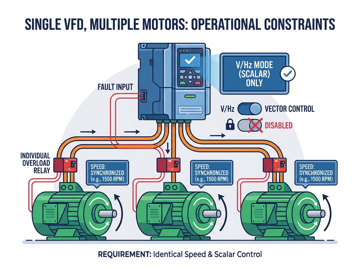
Running multiple motors from a single drive is a common cost-reduction strategy in plant design. However, it introduces significant operational risks if engineers misapply the concept. Plant managers often attempt this layout to streamline system architecture and simplify panel construction. For applications like parallel cooling fans, conveyor banks, or synchronized irrigation pumps, consolidating drives saves valuable panel space. You also reduce upfront capital drastically by purchasing fewer main components.
However, you cannot simply wire multiple motors in parallel and press start. Designing a shared-drive system demands rigorous engineering oversight. This guide evaluates the technical feasibility, strict sizing rules, and necessary hardware protections. You will learn how to safely run multi-motor setups. We will ensure you avoid compromising system reliability or voiding manufacturer warranties. You will discover the exact load calculations needed to maintain safe operation and protect your equipment long-term.
Key Takeaways
A single drive can run multiple motors, but only if all motors operate simultaneously at the same speed.
The drive must be sized based on the total Full Load Amperage (FLA) of all motors combined, plus a 10–20% safety margin.
Advanced control modes (like Sensorless Vector) must be disabled; the drive must operate in standard V/Hz (scalar) mode.
Individual thermal overload protection is strictly required for each motor, as the drive can only monitor total current.
The Business Case: Evaluating Cost Savings vs. Operational Risk
You must define strict success criteria before adopting a multi-motor layout. A single-drive setup only works when conditions align perfectly. Identical motors yield the best results. Loads must parallel each other exactly. Speed requirements must remain identical across all connected assets. If one motor needs to run at 30 Hz while another runs at 60 Hz, you must use separate drives. You cannot split frequencies from a single output terminal.
Engineers often pursue this layout for its significant capital expenditure (CapEx) advantages. Hardware costs drop immediately when you buy one large inverter instead of four smaller ones. Control enclosures shrink in size, requiring less floor space. Network communications simplify drastically. You use fewer nodes on the PLC network, which reduces programming time and cable runs. Maintenance teams also manage fewer core components during routine inspections.
Despite these savings, you must weigh the operational risks. The single point of failure presents a massive drawback. If the central drive faults, all connected motors shut down instantly. This ruins high-availability architectures. Redundant systems fail entirely under this design. Trustworthiness is key when designing critical infrastructure. You must balance initial financial savings against severe downtime risks. A multi-motor layout is fundamentally incompatible with processes requiring continuous, uninterrupted operation.
Table: Single Drive vs. Multi-Drive Architecture Comparison
Architecture Characteristic
Single Drive (Multi-Motor)
Individual Drives (Per Motor)
Initial Hardware Cost
Generally lower (one large unit)
Higher (multiple smaller units)
Panel Space Required
Minimal footprint
Requires larger or multiple enclosures
System Redundancy
None (Single point of failure)
High (One fault isolates one motor)
Individual Motor Speed Control
Impossible (All run at same frequency)
Full independent control
Maintenance Complexity
Fewer nodes, but complex fault tracing
More nodes, but easy fault isolation
Fundamental Limits of VFD Operating Principles in Multi-Motor Setups
Understanding standard VFD operating principles is crucial for parallel configurations. Modern drives rely heavily on precise current feedback to optimize motor torque. The internal microprocessor constantly reads the return current to adjust output pulses. Connecting multiple motors blends this feedback into a chaotic, aggregate signal. The drive processor cannot distinguish the current draw of Motor A from Motor B. It only sees a single, unified load.
This blended feedback explains why advanced vector control fails completely here. Sensorless Vector and Closed-Loop Vector modes require highly accurate mathematical models. The drive builds these internal models based on specific rotor dynamics and stator resistance. Multiple distinct rotors confuse the processor entirely. It cannot calculate precise slip compensation for three or four separate loads simultaneously. Attempting to use vector control usually results in erratic motor behavior, harsh vibrations, and nuisance overcurrent trips.
To operate safely, you must lock the drive into Volts/Hertz (V/f) scalar control. The scalar requirement is non-negotiable for parallel setups. Scalar mode blindly outputs a fixed ratio of voltage and frequency. It ignores individual motor slip entirely. It does not attempt to optimize torque based on feedback. This rigid output keeps the system stable. You sacrifice low-speed torque and dynamic responsiveness, but you gain the ability to spin multiple shafts reliably.
Relies on back-EMF and mathematical rotor modeling. Multiple rotors create chaotic, unreadable feedback.
Closed-Loop Vector
Strictly Prohibited
Requires dedicated encoder feedback from a single shaft. Cannot process multiple encoder inputs for one output.
Crucial Sizing Rules for a Single Industrial VFD
Sizing an industrial VFD for a parallel application requires strict adherence to amperage rules. You must abandon traditional sizing habits. Never size the drive by combined Horsepower (HP) or kilowatts (kW). Motor efficiencies and power factors vary. Three 5 HP motors might pull significantly more current than a single 15 HP motor. You must focus entirely on the nameplate Full Load Amperage (FLA) of every connected device.
The sizing formula demands precision and foresight. Engineers must calculate the total aggregate load carefully.
Step 1: Locate the nameplate FLA on every motor in the parallel circuit.
Step 2: Add the FLA values together (Motor 1 FLA + Motor 2 FLA + Motor N FLA).
Step 3: Calculate a mandatory 10% to 20% safety margin based on the total sum.
Step 4: Select a drive with a continuous output current rating exceeding this final calculated value.
This safety buffer handles varying cable lengths and minor mechanical load imbalances. It also protects the inverter components from premature thermal degradation.
You must also analyze inrush current considerations carefully. Staggering motor starts is incredibly dangerous in this architecture. Suppose the drive is already running three motors at full speed. You suddenly close a downstream contactor to bring a fourth motor online. Massive inrush current immediately hits the active inverter. Across-the-line starting pulls Locked Rotor Amps (LRA), which can reach 600% of the motor's normal FLA. The drive will trigger a catastrophic overcurrent fault instantly. Unless the drive is massively oversized to absorb this spike, you must start and stop all motors simultaneously.
Parallel systems possess a dangerous electrical blind spot. Because the drive only sees total aggregate output current, it cannot protect individual motors from mechanical binds. Imagine a system driving four identical fans. Each fan draws 10 Amps. The total load is 40 Amps, and the drive overload trips at 45 Amps. One fan bearing seizes. That specific motor stalls and its current spikes to 25 Amps. The other three fans continue drawing 10 Amps each. The total system current reaches 55 Amps. The drive trips and protects the system.
Now, consider a subtler bind. The failing fan spikes to 14 Amps instead of 25 Amps. The total current hits 44 Amps. This falls below the drive's 45 Amp trip threshold. The drive keeps running smoothly. It has no idea an anomaly exists. The struggling 14 Amp motor quickly overheats, melts its winding insulation, and burns out completely.
Plant safety protocols and NEC/IEC standards demand strict implementation realities to solve this flaw. You must install individual thermal overload relays on the output side. Place these devices between the drive and each respective motor. You can use traditional bimetallic overloads or modern electronic motor protection circuit breakers (MPCBs).
Wiring the fault circuit properly ensures complete system safety. You must integrate these downstream protectors into the drive's control logic.
Install the thermal overloads inside the main control enclosure or in local disconnect boxes.
Locate the Normally Closed (NC) auxiliary contacts on every overload relay.
Wire all the auxiliary contacts in a continuous series daisy-chain.
Route this series circuit back to the drive's control terminal block.
Terminate the circuit into the drive's "External Fault," "Enable," or "Safe Torque Off (STO)" digital input.
If any single motor overheats, its specific relay opens the circuit. The drive detects the open circuit immediately and safely shuts down the entire system, preventing catastrophic fire or equipment loss.
Hardware Evaluation: Adapting the SD3300 Vector Frequency Inverter
Hardware selection dictates the long-term success of multi-motor layouts. When evaluating options, buyers must prioritize drives featuring robust scalar modes and high overload capacities. You cannot rely on basic commercial HVAC drives for heavy industrial parallel loads. You need rugged power electronics capable of sustaining prolonged current swells.
Applying the SD3300 vector frequency inverter as an evaluation model reveals several necessary checks. While the SD3300 excels at high-torque vector control, you must verify its parameter structure. Engineers must toggle it easily from its default vector mode to a rigid V/f curve. Confirm the parameter manual allows disabling of slip compensation and automatic tuning features. The drive must operate blindly and reliably to support multiple rotors without triggering internal logic faults.
Output filtering needs require intense scrutiny. Parallel setups increase total cable lengths exponentially. Running 100 feet of cable to four separate motors creates 400 feet of total capacitive burden on the inverter. This capacitance generates high-frequency charging currents that stress the drive's IGBTs. It also amplifies reflected wave phenomenons (voltage ringing) at the motor terminals, which destroys winding insulation rapidly.
Evaluate these filtering solutions before finalizing your panel design:
Output Line Reactors: Install a 3% or 5% reactor at the drive output to dampen voltage spikes and slow the capacitive charging current.
dV/dt Filters: Use these when combined cable lengths exceed 500 feet. They clip dangerous voltage peaks significantly better than standard reactors.
Sine Wave Filters: Mandatory for extreme cable lengths. They convert the drive's PWM output back into a near-perfect sine wave, protecting older motors from insulation failure.
Conclusion
Running multiple motors on one drive remains a highly specific, niche engineering solution. It is not a universal design hack. When implemented correctly, it condenses panel footprints and streamlines system layouts for synchronized loads like conveyor banks and parallel fans. However, you face steep penalties for cutting corners on protective hardware.
We recommend engineers verify the total system FLA precisely before choosing a chassis size. You must confirm V/f mode compatibility within the chosen inverter's parameter set. Finally, source downstream thermal overload contactors early in the design phase. Integrate these components before finalizing the panel Bill of Materials (BOM). Rigorous planning ensures your parallel system runs efficiently, safely, and predictably.
FAQ
Q: Can I run different sized motors on the same VFD?
A: Yes, but only in V/f (scalar) mode. The drive will output a fixed voltage and frequency regardless of motor size. However, we highly recommend keeping motor sizes relatively close. Extreme impedance mismatches cause uneven current sharing. A tiny motor might suffer insulation stress if paired with massive parallel loads.
Q: Can I start and stop individual motors while the VFD is running?
A: We strictly advise against this practice. Closing a contactor on a running drive pulls massive across-the-line starting current (Locked Rotor Amps). This sudden spike will trigger an overcurrent fault instantly. You can only do this if you massively oversize the VFD to absorb the incoming inrush current without tripping.
Q: Will I save money on energy costs with this setup?
A: No. While you save on initial hardware expenses and panel space, operational energy consumption remains identical. It might perform slightly worse than individual drives because you lose the advanced energy-optimizing vector algorithms. The drive must run in basic V/f mode, which cannot optimize flux current dynamically for changing loads.