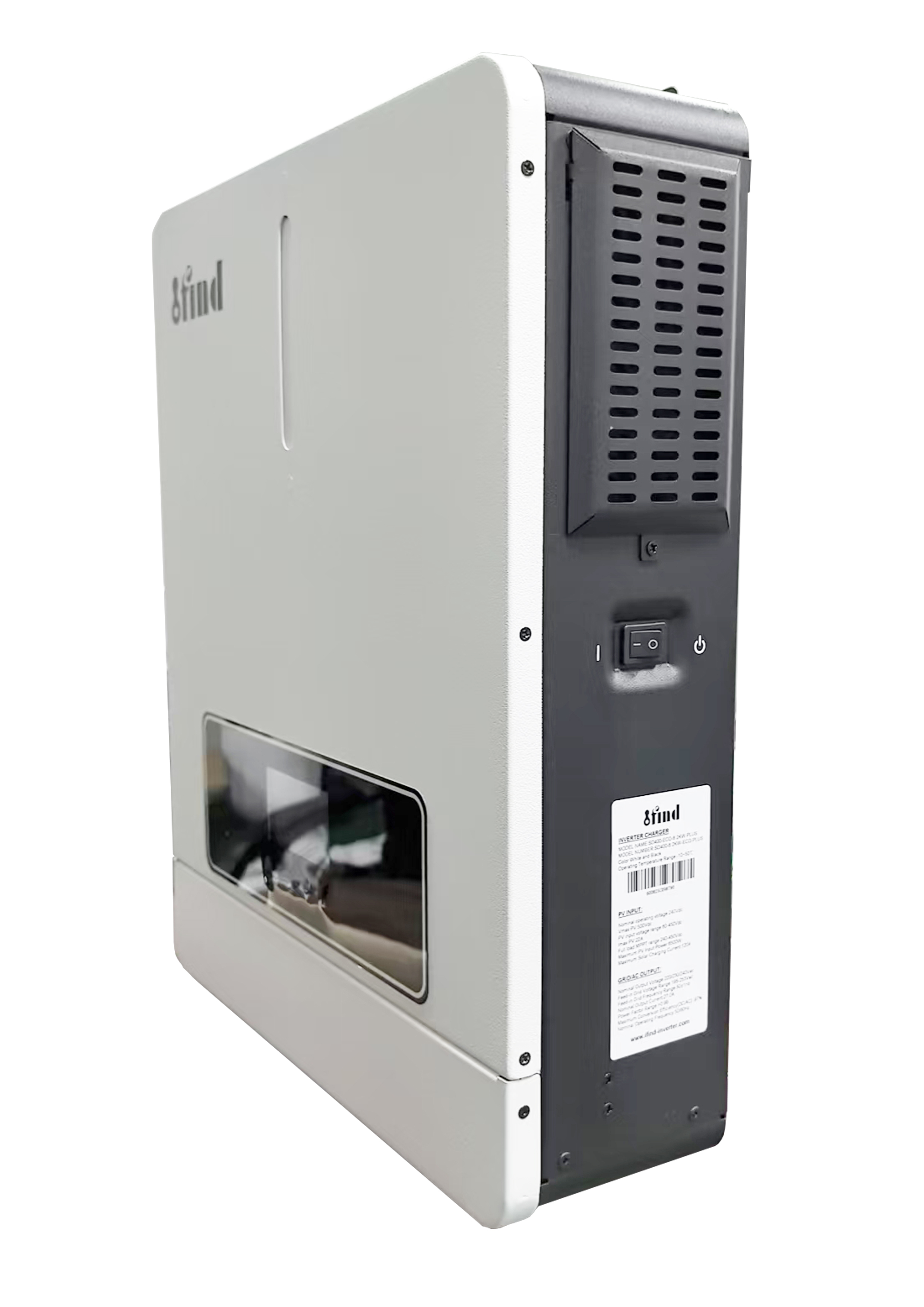
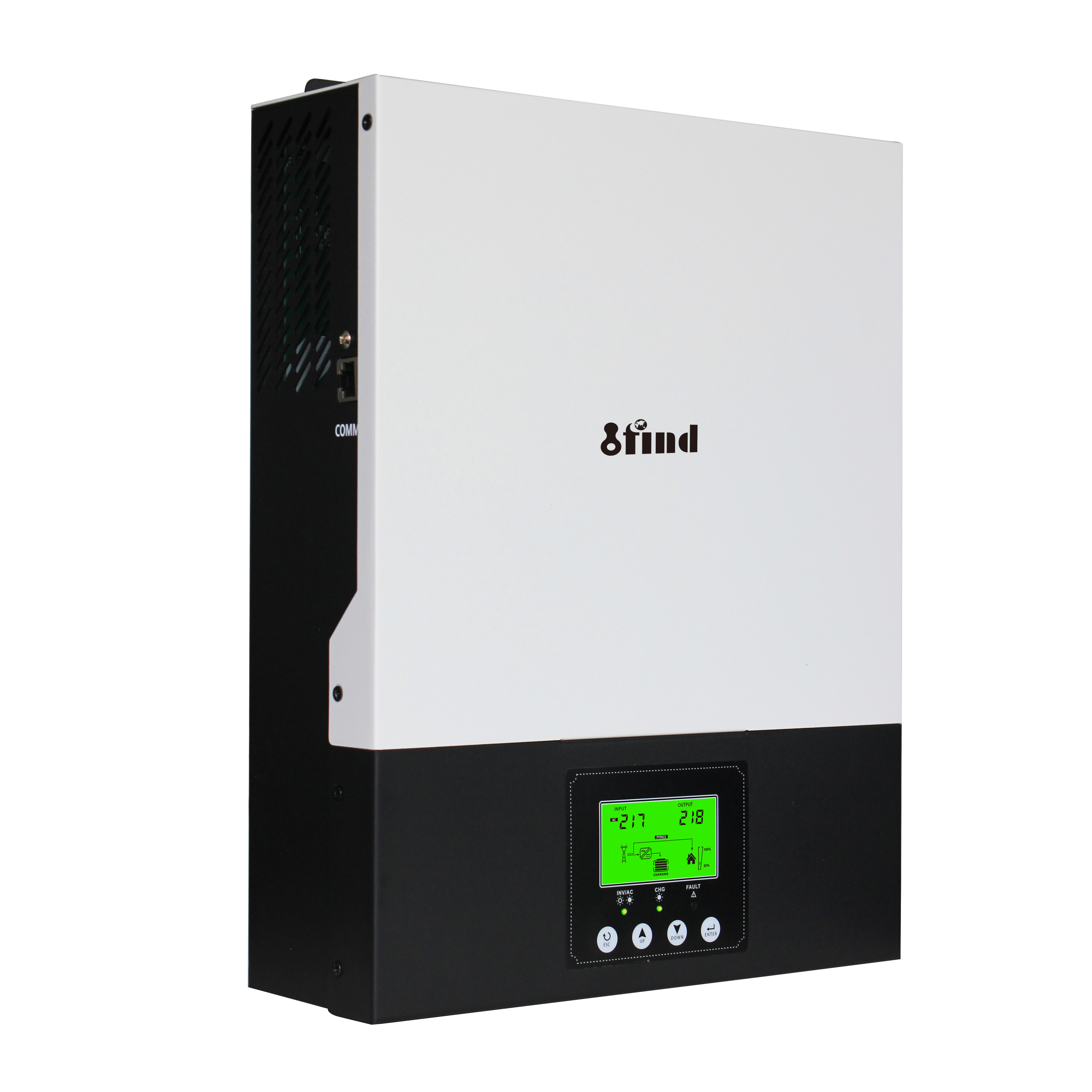
8.2kW Pure Sine Wave Off-Grid Hybrid Solar Inverter with MPPT
Designed for residential and light-commercial off-grid systems, this 8.2kW hybrid solar inverter combines pure sine wave AC output, MPPT solar charging, battery charging, and utility or generator input in one unit. Battery-free daytime operation, dual-output load management, and WiFi/GPRS monitoring options give installers more flexibility when configuring solar, storage, and backup power sources.
Exclusive Appearance Designed by Mercedes-Benz Designers Solarman APP Remote Monitoring for IOS and Android Touch Button IP65 Rated 5 Years Warranty
7 * 24 Hours Engineer Online Support
Remote technical support
Special 8.2KW
Technology support of 8.2KW single phase 220V off grid solar mppt hybrid inverter
Phase
1-phase
Maximum PV Input Power
6200W
6200W
6500W
Rated Output Power
3600W
4200W
6200W
Maximum Solar Charging Current
120A
GRID-TIE OPERATION
PV INPUT (DC)
Nominal DC Voltage/Maximum DC Voltage
360/500VDC
Start-up Voltage/Initial Feeding Voltage
60VDC/90VDC
MPPT Voltage Range
60~450VDC
Maximum Input Current
1/18A
1/22A
GRID OUTPUT(AC)
Nominal Output Voltage
220/230/240VAC
Output Voltage Range
195.5~253VAC
Nominal Output Current
15.7A
18.2A
27.0A
Power Factor
>0.99
EFFICIENCY
Maximum Conversion Efficiency(DC/AC)
98%
TWO LOAD OUTPUT POWER
Full Load
3600W
4200W
6200W
Maxium Main Load
3600W
4200W
6200W
Maxium Second Load(battery mode)
1200W
1400W
2067W
Maxium Load Cut Off Voltage
26VDC
26VDC
52VDC
Maxium Load Return Voltage
27VDC
27VDC
54VDC
OFF-GRID OPERATION
AC INPUT
AC Start-up Voltage/Auto Restart Voltage
120-140VAC/180VAC
Acceptable Input Voltage Range
90-280VAC or 170-280VAC
Frequency Range
49~51±1HZ
Maximum AC Input Current
30A
30A
40A
PV INPUT (DC)
Nominal DC Voltage/Maximum DC Voltage
360/500VDC
MPPT Voltage Range
60~450VDC
Maximum Input Current
1/18A
1/22A
BATTERY MODE OUTPUT (AC)
Nominal Output Voltage
220/230/240VAC
Output Waveform
Pure sine wave
Efficiency(DC to AC)
94%
HYBRID OPERATION
PV INPUT (DC)
Nominal DC Voltage/Maximum DC Voltage
360/500VDC
Start-up Voltage/Initial Feeding Voltage
90VDC/120VDC
MPPT Voltage Range
60~450VDC
Maximum Input Current
1/18A
1/22A
GRID OUTPUT (AC)
Nominal Output Voltage
220/230/240VAC
Output Voltage Range
195.5~253VAC
Nominal Output Current
15.7A
18.2A
27.0A
AC INPUT
AC Start-up Voltage /Auto Restart Voltage
120-140VAC/180VAC
Acceptable Input Voltage Range
90-280VAC or 170-280VAC
Maximum AC Input Current
30A
30A
40A
Maximum AC Charging Current
100A
GENERAL
PHYSICAL
Dimension, DxWxH(mm)
420*350*110
Carton Dimension,D XW XH(mm)
500*415*180
Net Weight (kgs)
8
8.5
9
Gross Weight(kgs)
9
9.5
10
INTERACE
Communication Port
RS232/RS485/WIFI/GPRS/LITHIUM BATTERY
ENVIRONMENT
Humidity
5% to 95% Relative Humidity(Non ~ condensing)
Operating Temperature
-10℃~50℃
STANDARD
Compliance Safety
CE
IFIND 8.2KW single phase 220V off grid solar mppt hybrid inverter, energy storage battery systems, etc, and Amensolar provides the services of system design, project construction and maintenance, and third-party operation and maintenance.Hybrid on grid Inverter products charger combines the functions of an inverter, solar charger, and battery charger, providing uninterrupted power supply support in a portable size.
With dual PV input and dual MPPT voltage tracking, this hybrid inverter offers maximum efficiency and flexibility. It features different working modes, including purple photovoltaic mode, red battery mode, and blue utility mode, allowing you to adapt to various power sources and optimize energy usage.it will be very popular all over the world.
Product Overview
The 8.2kW Pure Sine Wave Off-Grid Hybrid Solar Inverter with MPPT brings solar charging, battery charging, AC conversion, and backup AC input into one unit. It is intended for single-phase solar systems that require flexible access to photovoltaic power, battery storage, utility power, or a compatible generator.
Pure sine wave output supports the normal operation of household appliances, office equipment, lighting, refrigeration, and other AC loads within the inverter’s rated continuous and starting capacity. The unit can also operate without a battery when available PV power and the selected working mode can support the connected loads.
Built-in MPPT charging, dual-load outputs, and optional remote monitoring give installers more control over how solar energy is collected, stored, and supplied.
Key Features
Pure Sine Wave Output
The inverter produces pure sine wave AC power with an output power factor of 1.0. This output format is suitable for a wide range of conventional appliances and electronic equipment, provided that both continuous power and startup demand remain within the inverter’s limits.
Integrated MPPT Charging
The built-in MPPT charge controller tracks the operating point of the PV array and manages solar charging without requiring a separate external solar controller. The published maximum PV input voltage is 500VDC; final string design must follow the confirmed datasheet and the open-circuit voltage of the selected modules.
Battery-Free Operation
Where sufficient solar input is available, the inverter can supply connected loads without an installed battery. This option may suit daytime loads or projects where battery storage will be added later. Output stability will still depend on PV conditions and the configured backup source.
Dual-Output Design
Two load outputs allow an installer to separate priority loads from lower-priority circuits. For example, lighting, communication equipment, and refrigeration can be placed on the main output, while less critical loads use the secondary output.
The two outputs do not provide two independent 8.2kW power sources. Total connected demand must remain within the inverter’s confirmed load limits.
Multiple Power Sources
The inverter can work with solar panels, battery storage, utility power, or a compatible generator. This allows the system designer to select an operating strategy based on local grid conditions, solar availability, backup requirements, and battery capacity.
Technical Specifications
Phase
1-phase
Maximum PV Input Power
6200W
6200W
6500W
Rated Output Power
3600W
4200W
6200W
Maximum Solar Charging Current
120A
GRID-TIE OPERATION
PV INPUT (DC)
Nominal DC Voltage/Maximum DC Voltage
360/500VDC
Start-up Voltage/Initial Feeding Voltage
60VDC/90VDC
MPPT Voltage Range
60~450VDC
Maximum Input Current
1/18A
1/22A
GRID OUTPUT(AC)
Nominal Output Voltage
220/230/240VAC
Output Voltage Range
195.5~253VAC
Nominal Output Current
15.7A
18.2A
27.0A
Power Factor
>0.99
EFFICIENCY
Maximum Conversion Efficiency(DC/AC)
98%
TWO LOAD OUTPUT POWER
Full Load
3600W
4200W
6200W
Maxium Main Load
3600W
4200W
6200W
Maxium Second Load(battery mode)
1200W
1400W
2067W
Maxium Load Cut Off Voltage
26VDC
26VDC
52VDC
Maxium Load Return Voltage
27VDC
27VDC
54VDC
OFF-GRID OPERATION
AC INPUT
AC Start-up Voltage/Auto Restart Voltage
120-140VAC/180VAC
Acceptable Input Voltage Range
90-280VAC or 170-280VAC
Frequency Range
49~51±1HZ
Maximum AC Input Current
30A
30A
40A
PV INPUT (DC)
Nominal DC Voltage/Maximum DC Voltage
360/500VDC
MPPT Voltage Range
60~450VDC
Maximum Input Current
1/18A
1/22A
BATTERY MODE OUTPUT (AC)
Nominal Output Voltage
220/230/240VAC
Output Waveform
Pure sine wave
Efficiency(DC to AC)
94%
HYBRID OPERATION
PV INPUT (DC)
Nominal DC Voltage/Maximum DC Voltage
360/500VDC
Start-up Voltage/Initial Feeding Voltage
90VDC/120VDC
MPPT Voltage Range
60~450VDC
Maximum Input Current
1/18A
1/22A
GRID OUTPUT (AC)
Nominal Output Voltage
220/230/240VAC
Output Voltage Range
195.5~253VAC
Nominal Output Current
15.7A
18.2A
27.0A
AC INPUT
AC Start-up Voltage /Auto Restart Voltage
120-140VAC/180VAC
Acceptable Input Voltage Range
90-280VAC or 170-280VAC
Maximum AC Input Current
30A
30A
40A
Maximum AC Charging Current
100A
GENERAL
PHYSICAL
Dimension, DxWxH(mm)
420*350*110
Carton Dimension,D XW XH(mm)
500*415*180
Net Weight (kgs)
8
8.5
9
Gross Weight(kgs)
9
9.5
10
INTERACE
Communication Port
RS232/RS485/WIFI/GPRS/LITHIUM BATTERY
ENVIRONMENT
Humidity
5% to 95% Relative Humidity(Non ~ condensing)
Operating Temperature
-10℃~50℃
STANDARD
Compliance Safety
CE
Solar and Backup Power Management
The inverter acts as the power-management point between the PV array, battery bank, AC backup source, and connected loads.
During periods of sufficient sunlight, PV energy can be used for load supply and battery charging according to the selected settings. When solar production falls, stored battery energy or the configured AC source can support the loads.
Utility or generator input can also provide battery charging when solar energy is insufficient. Input voltage, frequency, grounding arrangement, and generator waveform must comply with the final inverter specification.
Operating priorities should be configured during commissioning. An installer should base these settings on:
The daily load profile
Available PV power
Battery capacity and charge limits
Generator operating strategy
Required backup duration
Critical and non-critical load groups
This approach avoids relying on one default setting for projects with different energy requirements.
Dual-Output Load Management
Dual outputs provide a practical way to separate essential and discretionary loads.
Main Load Output
The main output can be assigned to circuits that should remain available for as long as the system has sufficient solar, battery, or backup AC power.
Typical examples include:
Lighting and communication equipment
Refrigerators and freezers
Security and monitoring systems
Computers and network devices
Selected household or office circuits
Secondary Load Output
The secondary output can be used for loads that may be disconnected earlier when battery voltage or available power falls below the configured threshold.
Possible loads include:
Non-essential sockets
Auxiliary lighting
Selected workshop equipment
Water heating or other discretionary loads
Actual cut-off and return conditions must be set according to the confirmed manual. Load allocation should account for both running power and startup current.
Monitoring and Communication
WiFi and GPRS connectivity are available for iOS and Android monitoring. The Solarman platform can be used to review system status, operating mode, and energy information when the correct communication module is installed.
Published communication interfaces include:
RS232
RS485
WiFi
GPRS
Lithium battery communication interface
The communication port does not automatically guarantee compatibility with every lithium battery. Before ordering, provide the battery brand, model, voltage, BMS protocol, and communication cable definition for verification.
WiFi or GPRS hardware may be supplied as an option depending on the order configuration. Confirm the included accessories in the quotation.
Application Scenarios
Off-Grid Homes
The inverter can form the control center of an off-grid residential system, combining solar generation, battery storage, and generator or utility backup. Household circuits must be selected according to the inverter’s continuous and surge capacity.
Shops and Small Offices
Pure sine wave output makes the unit suitable for lighting, computers, network devices, point-of-sale equipment, refrigeration, and other routine business loads. A load assessment is still required before connecting air conditioners, pumps, or compressors.
Farms and Remote Sites
The inverter can support remote buildings, farm offices, monitoring equipment, lighting, refrigeration, and other distributed loads where grid power is unavailable or unstable.
Motor-driven equipment should be checked separately because startup current can be considerably higher than its rated running power.
Light-Commercial Systems
Installers may use the unit in small workshops, service locations, telecom rooms, and other light-commercial applications. It is not a substitute for a three-phase industrial inverter, and suitability should be confirmed when the load includes large motors or continuous high-power machinery.
System Matching and Installation
Calculate Continuous and Starting Loads
Add the rated power of loads that may run at the same time. Pumps, compressors, refrigerators, air conditioners, and motors may require substantially more power during startup. Their surge demand must be checked against the confirmed inverter specification.
Check the PV String Voltage
Calculate the array’s open-circuit voltage at the lowest expected site temperature. The result must remain below the inverter’s confirmed maximum PV voltage.
The normal operating voltage of the array should also remain inside the MPPT range. Staying below the absolute maximum voltage alone is not sufficient for correct MPPT operation.
Verify Battery and BMS Compatibility
Confirm battery voltage, maximum charge current, discharge current, BMS protocol, and communication cable pinout. A physical RS485 connection does not guarantee that two devices use the same protocol.
Select the Required Protection
The final installation should include correctly rated DC and AC isolators, overcurrent protection, surge protection, earthing, and cable sizes appropriate for local regulations and installation conditions.
Use Qualified Installation Personnel
Installation, parameter setup, and commissioning should be completed by a qualified solar or electrical technician. The inverter must be isolated from PV, battery, utility, and generator sources before wiring or maintenance work begins.
Quality Control and Technical Support
IFIND maintains an ISO 9001 quality management system and reports CE certification and a BV field certification completed in 2024. Product-level certificates, model-specific test reports, manuals, and warranty terms can be supplied for project review.
According to IFIND’s quality-control information, inverter units are assembled and tested before packing and shipment. Technical support is available for parameter configuration, system matching, and application troubleshooting.
For stronger EEAT signals, the published page should also include:
A downloadable 8.2kW datasheet
The matching installation manual
A model-specific CE document
A battery compatibility list
A document revision date
“Reviewed by IFIND Applications Engineering” after technical approval
FAQs
What size solar array can be connected to this inverter?
PV array size depends on the inverter’s confirmed maximum PV power, maximum open-circuit voltage, MPPT range, and input-current limit. Module Voc must also be corrected for the lowest expected site temperature. Send the panel datasheet and planned series/parallel arrangement to IFIND for verification.
Can the inverter operate without a battery?
Yes, the product is designed to support battery-free operation when PV input and the selected working mode can supply the connected load. A battery or AC backup source is recommended where uninterrupted output is required during clouds, nighttime, or rapid load changes.
Which lithium batteries are compatible?
Compatibility depends on the battery voltage, charge limits, BMS protocol, and cable pinout. Provide the battery brand and exact model before ordering. The presence of an RS485 port alone does not confirm protocol compatibility.
Can it power air conditioners, refrigerators, or water pumps?
These loads may be supported if their combined running and startup demand remains within the inverter’s confirmed ratings. Compressor and motor startup current must be checked separately; appliance nameplate power alone may not be sufficient for system sizing.
Can a generator be used as the AC backup source?
A compatible generator can be connected when its voltage, frequency, grounding arrangement, and waveform meet the inverter’s AC input requirements. Generator capacity should cover the active loads and any simultaneous battery charging demand.
Do both load outputs provide 8.2kW?
No. The two outputs are intended for load grouping, not for doubling the inverter’s power. The combined load must remain within the inverter’s rated capacity, and the secondary output may have a lower limit or configurable cut-off condition.
Is WiFi or GPRS monitoring included?
WiFi and GPRS are listed as available monitoring options. Confirm whether the required module is included in the selected configuration and whether the Solarman platform is supported in the destination market.
Can the inverter be installed outdoors?
Outdoor suitability depends on the confirmed enclosure protection rating and the installation manual. Until the IP rating is verified, install the unit in a dry, ventilated location protected from direct rain, standing water, dust accumulation, and prolonged direct sunlight.
Need an 8.2kW Inverter Matched to Your System?
Send us your solar panel specifications, battery model, required AC output, and peak load. Our team will check system compatibility and prepare a practical configuration and quotation.
VF and VECTOR VFD inverter are already widely used in the world, The software is powerful and has a variety of control methods. Built-in PID, simple PLC; The inverter has the advantages of good speed regulation performance, high efficiency, stable performance, high reliability, strong overload capacity, etc., widely used in weaving, chemical fiber, printing and dyeing, plastics, light industry, machinery, chemical, steel, paper and other industries application
Solar inverter are already widely used in the world, Series applies to transforming three phase 380V or Single phase 220V submersible deep well pump into solar water pump system. It works this way that direct current produced by solar module inputs into alternating current which drives all kinds of water pump, especially for submersible well pump. Agricultural irrigation is carried out by directly connecting solar panels to drive water pumps
Elevators are already widely used in buliding,both for Synchronous and asynchronous motors the control functions and operation comfortable is much more and more important, our elevator inverter suitables for passenger and cargos, use the PMW and V/F ,vector control. Adopt international advanced V/F and vector technology Programmable Open Collector Output, Relay Output, Analog Output, Programmable Digital Input, Ensure the smooth and safe operation of the elevator.
Hybrid inverter are already widely used in the world, MPPT Solar Hybrid Inverter is a new all-in-one hybrid solar charge inverter, which integrates solar energy storage &means charging energy storage and AC sine wave output.It can be accessed to a variety of household appliances and office loads, power tools, industrial equipment, and electronic audio and video equipment, including refrigerators, lamps, televisions, fans, air conditioning and other AC loads